

I’d been thinking about setting up a homelab for a while. I wanted to play with my own projects without relying on cloud providers and to have my own storage space to store backups, as cloud storage prices are getting more expensive.
No homelab is complete without a proper networking setup. Given my experiences of performance and security issues with Internet Service Provider (ISP) routers, I wanted to have better control over the traffic on my home network. I decided to heavily focus traffic on wired connections, offload Wi-Fi, and ensure connections between devices over the local network are as fast as possible.
That’s where Mikrotik L009UiGS-RM comes into play. It has enough gigabit Ethernet ports to connect all my Ethernet devices. Power over Ethernet (PoE) is a nice bonus, as I can power my access point without a plug. The router has a small form factor, so I could mount it on the wall.
Know your ISP
Nevertheless, before I touched the router, I needed to find out how my ISP actually hands off the Internet connection. Two things decide your setup, and they are independent of each other:
- How the Wide Area Network (WAN) authenticates
- What kind of IPv4 address it gets
Find the answers to those two questions with a quick web search, or call your ISP’s support line.
IPoE or PPPoE
In Poland, some providers hand you an address over Dynamic Host Configuration Protocol (DHCP) through an Ethernet cable; this is Internet Protocol over Ethernet (IPoE). Others require a Point-to-Point Protocol over Ethernet (PPPoE) username and password, sometimes using a dedicated virtual local area network (VLAN). The right setup path depends entirely on this detail.
| Protocol | What your ISP gives you | Typical setup on MikroTik |
| IPoE | IP address, gateway, DNS via DHCP on the WAN. | Add a DHCP client on the WAN port. |
| PPPoE | Username and password, sometimes over a VLAN. | Create a VLAN if needed, then add a PPPoE client. |
Public or private WAN IPv4
The protocol only tells you how the router logs in.
Separately, check whether the address you receive is public or private. A private IPv4 address on the WAN port always means Carrier-Grade Network Address Translation (CGNAT) — your ISP shares one public IPv4 among many customers and translates it upstream, so nothing routes back to you unsolicited.
| Type of WAN IPv4 | What it means | Impact |
| Public | A routable address dedicated to your line. | Port forwarding, UPnP, and inbound connections work normally. |
| Private (CGNAT) | A shared address behind the ISP’s NAT. | Inbound connections generally don’t work unless the ISP sells a public IPv4 add-on. |
Warning: DS-Lite caveat
Dual-Stack Lite (DS-Lite) is the strictest form of CGNAT. The WAN gets no IPv4 address at all, only a public IPv6 address, and IPv4 traffic is tunnelled inside IPv6 to the ISP’s Address Family Transition Router (AFTR). The AFTR is the ISP-side endpoint of the IPv4-in-IPv6 tunnel in DS-Lite. It decapsulates subscriber IPv4 traffic, performs NAT, and routes it to the IPv4 Internet.
MikroTik routers support the DS-Lite tunnel itself, but don’t support automatically receiving the AFTR address needed to establish it. Because there’s no public IPv4 anywhere in the path, port forwarding, Universal Plug and Play (UPnP), inbound connections, and many remote-access tools stop working.
If your ISP offers DS-Lite or private IPv4, and you need inbound IPv4 access, ask about a paid public IPv4 add-on before you buy the router, or consider switching to another ISP.
For my fibre connection, the ISP uses PPPoE over VLAN 35 with a private IPv4 address. The rest of this post follows that path.
Setting up the MikroTik router
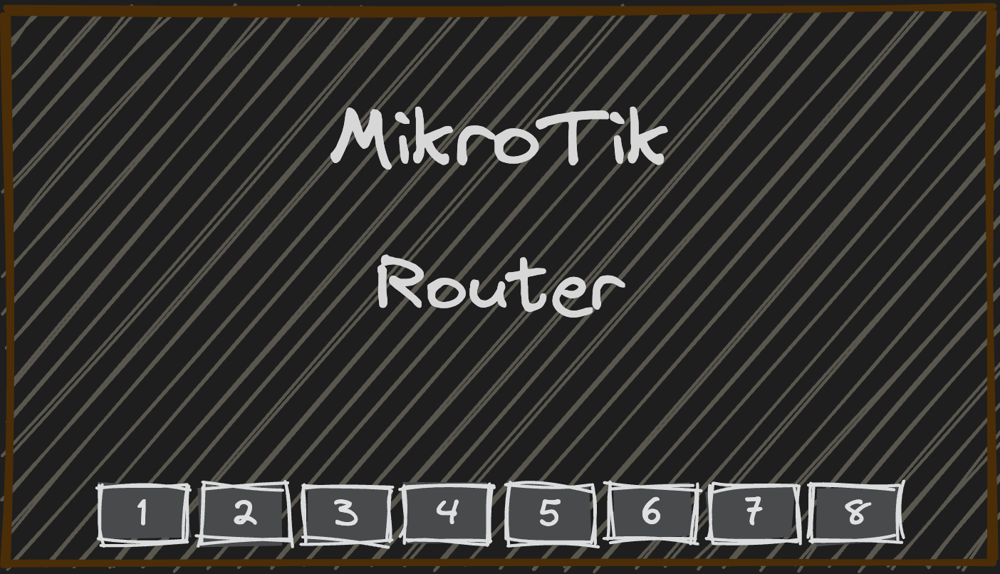
Start by powering on the router. Run an Ethernet cable from your computer to any LAN port on the MikroTik numbered two or higher. Leave port one free for the Optical Network Terminal (ONT) uplink — that becomes your WAN port later.
Open WinBox, switch to the Neighbors tab, and you should see the router listed at 192.168.88.1 (or its default MAC address). Log in using the admin user with no password, then change the default admin password immediately, because RouterOS still ships with blank or default credentials on some units.
After that, run through Quick Set just enough to give the router a stable management address and local subnet. You will come back later to replace the default wireless bridge with a cleaner configuration.
Getting Internet
The ONT sits at the edge of your home network. Run an Ethernet cable from the ONT to port one on the MikroTik. Once the link light comes up, the router can see the carrier signal.
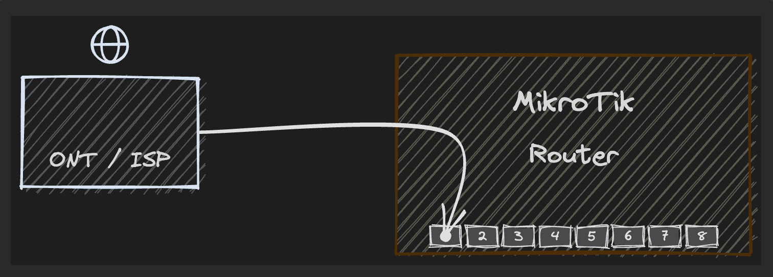
Some ISPs (mine included) bind the service to the MAC address of the router they shipped. Plug in a MikroTik with a different MAC, and the connection never authenticates, even when the VLAN and PPPoE settings are correct. The fix is to clone the original router’s MAC onto the WAN port. You can read that MAC from the sticker on the ISP router, or from its status page.
Clone it onto ether1. Because the VLAN interface and the PPPoE client both ride on ether1, they inherit this MAC automatically, so the ISP sees the address it expects.
# Check the current MAC before changing it
/interface ethernet print where name=ether1
# Flags: X - disabled, R - running, S - slave
#  #    NAME    MTU  MAC-ADDRESS        ARP     SWITCH
#  0  R ether1  1500 48:A9:8A:11:22:33  enabled switch1
# Clone the ISP router's MAC (replace with the address from its label)
/interface ethernet set ether1 mac-address=AA:BB:CC:DD:EE:FF# Confirm the WAN port now advertises the cloned MAC
/interface ethernet print where name=ether1
# Flags: X - disabled, R - running, S - slave
# # NAME MTU MAC-ADDRESS ARP SWITCH
# 0 R ether1 1500 AA:BB:CC:DD:EE:FF enabled switch1The cloned MAC persists across reboots. If you ever move the connection back to the original router, revert with /interface ethernet reset-mac-address ether1 to restore the port’s factory address.
My ISP tags the PPPoE traffic with VLAN 35. RouterOS needs a VLAN interface on top of ether1 before it can speak PPPoE. Add it with a descriptive name so future-you does not have to guess what vlan1 means.
/interface vlan add name=internet-vlan-35 vlan-id=35 interface=ether1/interface vlan print
# Flags: X - disabled, I - invalid, D - dynamic
# NAME MTU ARP VLAN-ID INTERFACE
# 0 internet-vlan-35 1500 enabled 35 ether1
With the VLAN in place, create the PPPoE client. Tell it to use the VLAN interface, accept the default route from the ISP, and use the ISP’s DNS servers. Leave the username and password empty at first — you will fill those in once the interface exists.
/interface pppoe-client add name=pppoe-out1 interface=internet-vlan-35 \
    add-default-route=yes use-peer-dns=yes disabled=no
/interface pppoe-client print
# Flags: X - disabled, I - invalid, R - running, D - dynamic
# NAME MTU INTERFACE USER SERVICE CALLER-ID ENCODING STATUS
# 0 pppoe-out1 auto internet-vlan-35 internet linkingNow set the credentials your ISP provided. The status should change from linking to connected within a few seconds.
/interface pppoe-client set pppoe-out1 user=YOUR_ISP_USERNAME password=YOUR_ISP_PASSWORD/interface pppoe-client print
# Flags: X - disabled, I - invalid, R - running, D - dynamic
# NAME MTU INTERFACE USER SERVICE CALLER-ID ENCODING STATUS
# 0 R pppoe-out1 auto internet-vlan-35 YOUR_ISP_USERNAME internet connectedConfirm the default route appeared. If the output shows pppoe-out1 as the gateway, traffic can reach the Internet.
/ip route print where dst-address=0.0.0.0/0
# Flags: D - dynamic; X - disabled, R - running, S - static; + - active
#  DST-ADDRESS     PREF-SRC  GATEWAY           DISTANCE
# D 0.0.0.0/0               pppoe-out1        1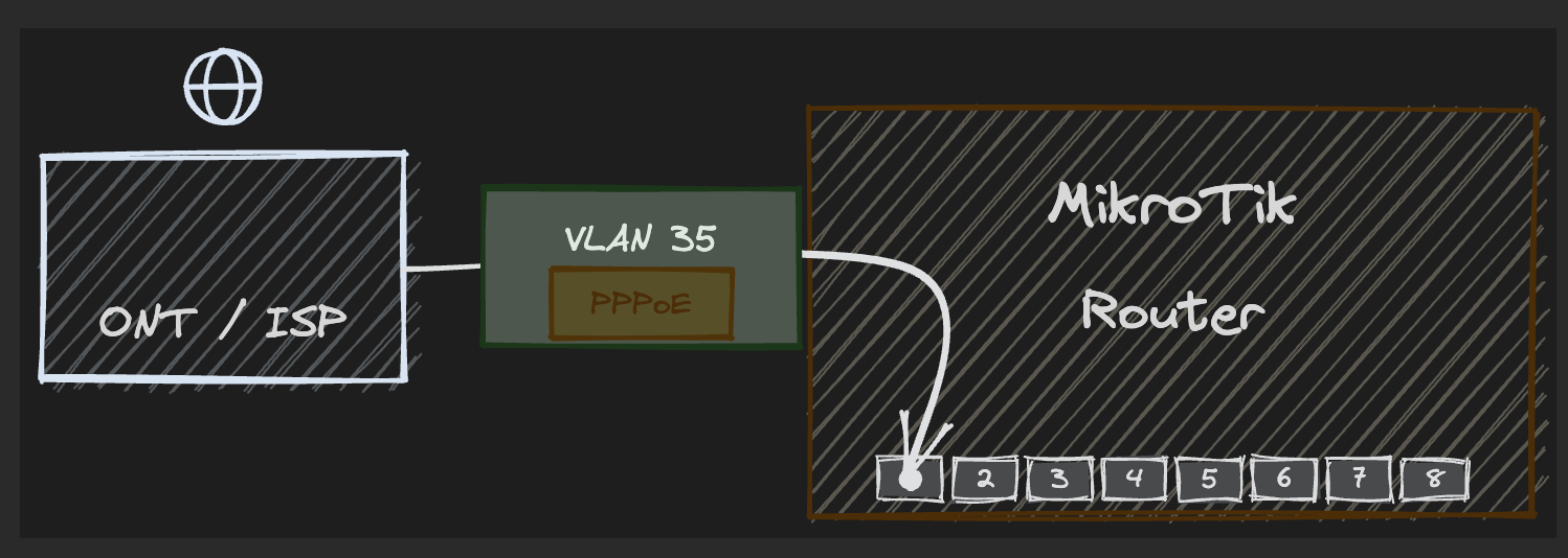
Let’s get a clean Wi-Fi setup
For wireless, I use a separate Wireless Access Point (WAP) powered over Ethernet. Port eight on the router feeds both data and power to the Access Point (AP). Enable PoE output on that port, and the WAP boots without a plug.
# Physical step: run an Ethernet cable from router port 8 (ether8) to the WAP AP.
# Then enable PoE output on port 8 so the WAP powers up:
/interface ethernet poe set ether8 poe-out=auto-on
/interface ethernet poe print
# NAME POE-OUT VOLTAGE CURRENT
# ether8 auto-on 24.0V 210mAManaging every AP individually does not scale. RouterOS includes CAPsMAN, which lets the router act as a central controller. You define a single security profile and datapath, plus channel templates for 2.4 GHz and 5 GHz, and the access point downloads that configuration automatically.
On the controller, create the shared objects first.
# --- On the router (CAPsMAN controller) ---
/interface wifi security add name=home-sec \
    authentication-types=wpa2-psk,wpa3-psk \
    wps=disable passphrase=YOUR_WIFI_PASSWORD
/interface wifi channel add name=ch-2ghz band=2ghz-n width=20mhz
/interface wifi channel add name=ch-5ghz band=5ghz-ac width=20/40mhz
/interface wifi datapath add name=home-dp bridge=bridge disabled=no
/interface wifi configuration add name=home-2g ssid=HomeNetwork \
    country=YOUR_COUNTRY security=home-sec channel=ch-2ghz datapath=home-dp mode=ap
/interface wifi configuration add name=home-5g ssid=HomeNetwork \
    country=YOUR_COUNTRY security=home-sec channel=ch-5ghz datapath=home-dp mode=ap
/interface wifi capsman set enabled=yes interfaces=bridge
/interface wifi provisioning add action=create-dynamic-enabled \
    master-configuration=home-2g supported-bands=2ghz-n
/interface wifi provisioning add action=create-dynamic-enabled \
    master-configuration=home-5g supported-bands=5ghz-ac
# Verify the controller is listening
/interface wifi capsman print
# enabled: yes
# package: wifi-qcom
# interfaces: bridge
# require-peer-certificate: no
# upgrade-policy: noneOn the access point, enable CAP mode and point the radios at the manager.
# --- On the wAP (CAP / managed AP) ---
/interface wifi cap set enabled=yes discovery-interfaces=bridge
/interface wifi set wifi1 configuration.manager=capsman disabled=no
/interface wifi set wifi2 configuration.manager=capsman disabled=no
# Verify the wAP has joined the controller
/interface wifi cap print
# enabled: yes
# discovery-interfaces: bridge
# caps-man-addresses:
# caps-man-names:Back on the controller, you should see dynamic radio entries appear. Each radio adopts the configuration that matches its band.
# Back on the controller, check that managed radios appeared
/interface wifi print
# Flags: D - dynamic
#    #    NAME                                              TYPE       ACTUAL-CONFIGURATION
#    0  D  cap1@2.4GHz                                       wifi       home-2g
#    1  D  cap1@5GHz                                         wifi       home-5g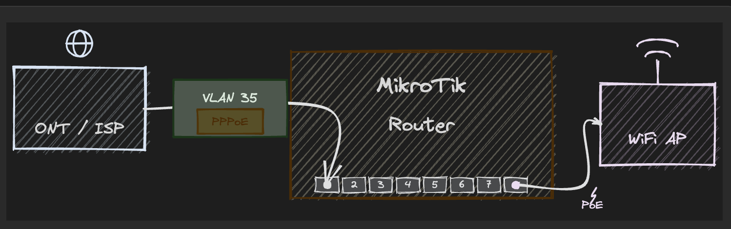
Understanding bufferbloat
Bufferbloat is excessive latency caused by overfilled packet queues inside network equipment. It shows up when a link becomes saturated, because large buffers hold packets instead of dropping or marking them quickly. Real-time traffic then waits behind bulk transfers.
Source: Bufferbloat.net
During a typical evening on the weekend, I noticed something strange. I was playing Counter-Strike, but then it started lagging due to ping fluctuations. It turned out an iOS update started on another device, and a phone began uploading photos to cloud backup.
The culprit was bufferbloat, meaning that the router’s queue filled and latency spiked, leaving game packets stuck behind a backlog of bulk traffic.
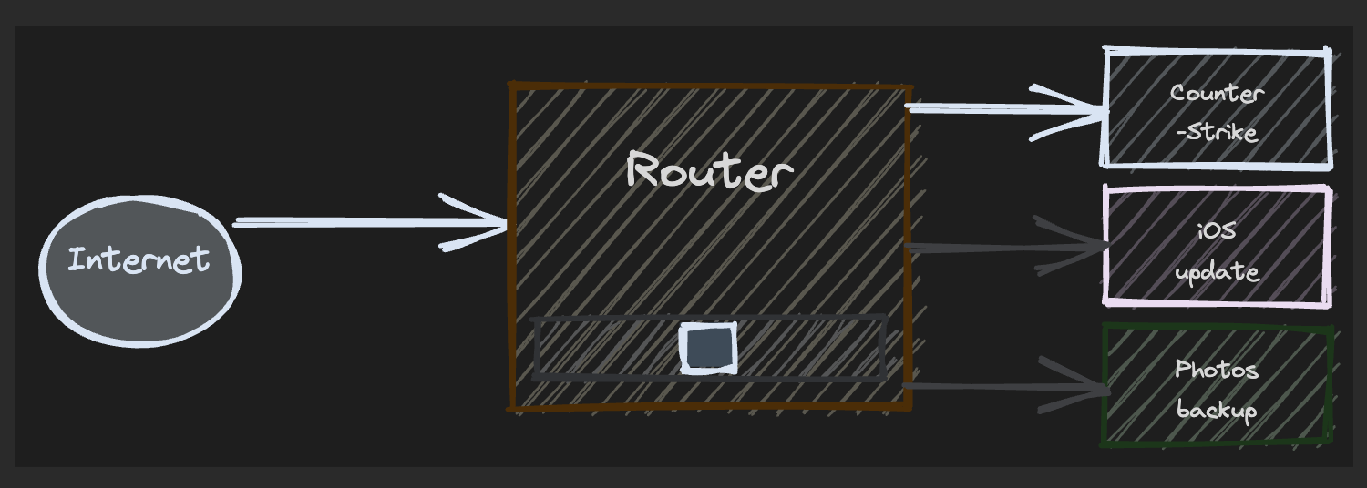
With no competing traffic, the latency stays low. The game sends small packets, and the queue rarely holds more than a frame or two.
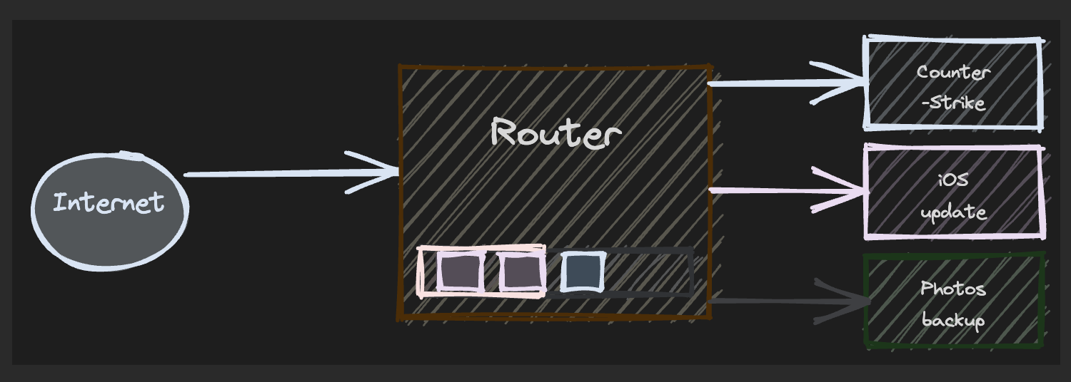
Then, a download starts from another device on the network. The buffers absorb the burst, but do not drain fast enough, so latency climbs as game packets wait behind the buffers.
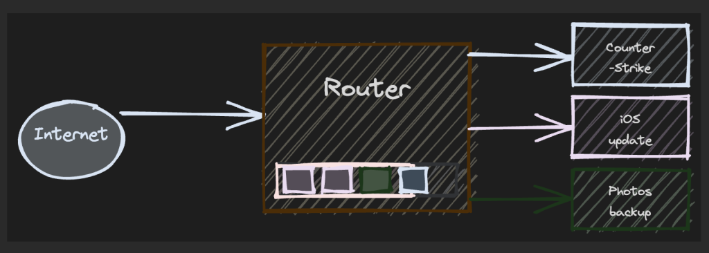
An upload joins the mix, and upload queues are usually the worst offenders on asymmetric links. The game now faces queuing in both directions.
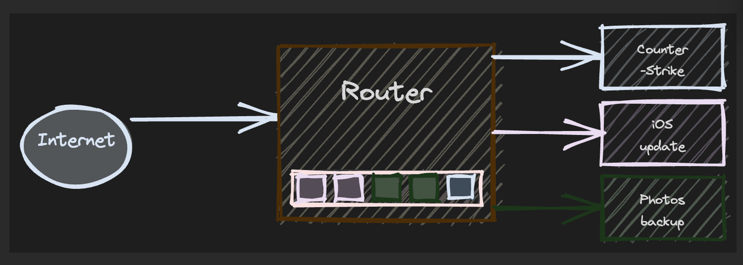
The result: The buffer is full. Even tiny game packets wait until the bulk traffic ahead of them clears, which shows up as rubber-banding and delayed voice chat.
You can measure this with online tests — I use the Cloudflare Speed Test. It reports both loaded and unloaded latency so you can read the bufferbloat grade directly. You can get a rough picture by running any speed test while pinging a stable host in a terminal.
FQ-CoDel to the rescue
RouterOS supports several queue disciplines. The default First In, First Out (FIFO) queue simply stores packets in the order it receives them. When the link is full, every flow waits behind every other flow. Fair/Flow Queue Controlled Delay (FQ-CoDel) splits traffic into many small flows and gives each one a fair turn, dropping packets that linger in the queue. This keeps latency low without complex firewall mangle rules.
| Queue discipline | How it handles congestion | Best for |
| FIFO (default-small) | One shared queue; first in, first out. | Low congestion, uniform traffic. |
| FQ-CoDel | Per-flow fairness with active delay control. | Gaming and VoIP on shared links. |
To use FQ-CoDel, first create a queue type, since RouterOS does not include one by default.
/queue type add name=fq-codel kind=fq-codel/queue type print where name=fq-codel
# Flags: * - default, X - disabled, I - invalid, D - dynamic
# 0 name="fq-codel" kind=fq-codel fq-codel-target=5ms fq-codel-interval=100ms \
# fq-codel-ecn=yes fq-codel-flows=1024 fq-codel-quantum=1514 \
# fq-codel-limit=10240 fq-codel-memlimit=32.0MiBThe default parameters are a sensible starting point. The target of 5ms defines the acceptable standing queue delay. The interval of 100ms matches a rough worst-case round-trip-time (RTT) budget.
The important part is the max-limit. It must sit below your real line rate, not at it. If you shape at 100% of the link, the ISP’s equipment still saturates first, and the bloated queue forms there, outside your control. A common rule of thumb is to set the limit at about 90 to 95% of the measured download and upload speeds. That keeps the bottleneck on your router, where FQ-CoDel can actually manage the queue.
Replace the placeholders below with your own measured values: The first number is upload, the second is download.
/queue simple add name=shaping target=pppoe-out1 max-limit=<0.9xUPLOAD>M/<0.9xDOWNLOAD>M \
    queue=fq-codel/fq-codel total-queue=fq-codel
/queue simple print where name=shaping
# Flags: X - disabled, I - invalid; D - dynamic
# 0 name="shaping" target=pppoe-out1 dst-address=0.0.0.0/0 \
# interface=all parent=none priority=8/8 queue=fq-codel/fq-codel \
# limit-at=0/0 max-limit=<0.9xUPLOAD>M/<0.9xDOWNLOAD>M burst-limit=0/0 burst-threshold=0/0 \
# burst-time=0s/0s bucket-size=0.1/0.1 total-queue=fq-codelSimple queues do not apply to packets that are fast-tracked by the firewall. Fast track bypasses the queue subsystem for performance. For the queue to work, disable the fasttrack rule or remove it entirely.
# Find the fasttrack rule
/ip firewall filter print where action=fasttrack-connection
If a rule exists, either disable it or remove it. Be careful: removing fasttrack increases Central Processing Unit (CPU) load on high-throughput links. On a modern MikroTik with a CPU that can handle line-rate forwarding, the trade-off is worth it for improved latency.
# Option A: disable the rule
/ip firewall filter disable [find action=fasttrack-connection]

# Option B: remove it entirely
/ip firewall filter remove [find action=fasttrack-connection]
After making the change, run the Cloudflare Speed Test again. You should see the bufferbloat grade improve, especially under upload load.
This post originally appeared on Rafał Opiłowski’s blog.
Rafał Opiłowski is a second-year Master’s student in Computer Science, specializing in Data Science at the Polish-Japanese Academy of Information Technology (PJAIT). In 2026, he worked as a Software Engineer at Dell Technologies, contributing to Kubernetes-based infrastructure. He writes about software engineering and his passion for technology at justsomebody.dev.
The views expressed by the authors of this blog are their own and do not necessarily reflect the views of APNIC. Please note a Code of Conduct applies to this blog.
Wow. It’s 2026 and no mention of how to set up ipv6 with your ISP.
By all accounts MikroTik have good support for ipv6 and APNIC are strong advocates of ipv6, so why such a glaring oversight?
Hey Mark, thanks for reading the post, and for your comment. This guest post looked specifically at the challenges faced by the author, and how they resolved those challenges. If you’re interested in seeing how IPv6 can be deployed in a home network, you might be interested in Terry Sweetser’s post about ‘Project IPv6’: https://blog.apnic.net/2026/04/03/project-ipv6-first-a-case-study-in-achieving-an-80-native-ipv6-soho-network/
Unfortunately Mikrotik has very good hardware, but the worst software for supporting IPv6-Only with IPv4aaS deployments, such as the one becoming most common 464XLAT. We have tried hard to get that from Mikrotik, never get a response …, despite how easy is to incorporate CLAT and having several implementations in Open Source. So clearly, Mikrotik can’t be recommended at all in today’s world.