

Congestion control is important for adapting the sending rate when network conditions fluctuate — a common problem among wireless technologies like Wi-Fi 6 and 5G.
The time from when network conditions change to when the congestion control algorithm finally adapts to the new rate is the control loop. Existing literature on congestion control, although vast, ignores the transient behaviour during this control loop, specifically:
- How congestion signals are carried along the same path as data packets.
- When throughput drops and latency goes up, congestion signals — like timestamps or losses — take more time to reach the sender.
- Because the congestion control algorithms (CCAs) cannot learn of the change in network conditions, the connection will experience latency spikes that are problematic for real-time and latency-sensitive applications (for example, video conferencing).
Our research at Tsinghua University shows it’s possible to decouple the control loop from the full path that data packets traverse using a novel router management mechanism, Zhuge, and in the process protect control signals from experiencing the full latency of full, often buffer-bloated queues.
By explicitly bypassing the bloated queue on the bottleneck routers, delay spikes experienced by video traffic can be significantly reduced; in up to 95% of scenarios when the available bandwidth drops, users will no longer experience stutters.
What is the control loop of congestion control?
Wireless technologies, even as advanced as Wi-Fi 6 (802.11ax) or 5G (mmWave), still suffer poor tail latencies due to fluctuating bandwidth availability. The problem arises because CCAs at end hosts fail to react quickly to these fluctuations.
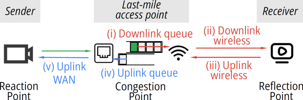
For example, in Figure 1, let’s assume there is rapid onset of congestion at the last-mile access point. When the green shaded packet arrives at the congestion point and observes a long queue, it will go through what is called a control loop, which requires:
- Going through the queue.
- Getting transmitted to the receiver.
- The corresponding feedback is delivered from the receiver to the access point.
- Going through the uplink queue.
- Going through the uplink WAN to the sender.
Since the shortest time for the sender to be notified is one full control loop including segments (i)-(v), an end host-based CCA cannot quickly adapt to transient bandwidth fluctuation.
Control loop inflation
The duration of congestion is further amplified when the available bandwidth (ABW) fluctuates. This is caused by the transient mismatch of the sending rate at the sender and ABW at the bottleneck queue.
Figure 2 shows the transient mismatch from the view of the bottleneck queue. When the ABW of one latency-sensitive flow suddenly drops by κx at the bottleneck router (the solid blue line), it takes one control loop τ for the CCA to reduce its sending rate (the green dashed line). During this period, the bottleneck queue still receives packets from the sender at its original sending rate. Thus, the queue builds up due to these excessive packets, as shown in the red shadow.
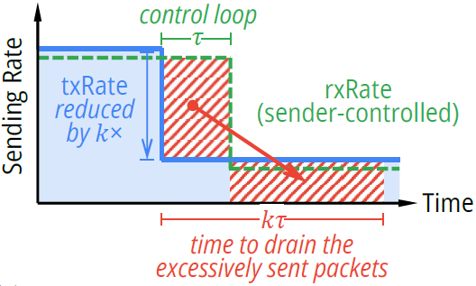
Packets that arrive at the bottleneck queue during the control loop τ would need κτ in total to be sent out. During this period, all packets sent out experience an increased latency, degrading the user’s experience.
Therefore, the transient increase of latency depends on how severely the ABW fluctuates (κ), and how soon the sender reacts (τ).
We can do better
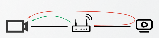
From our research, we’ve shown that decoupling the control loop from the full path that data packets traverse can protect control signals from experiencing the full latency of filling, often buffer-bloated queues. A carefully designed router (for example, Wi-Fi access points) observing a filling downlink queue ((i) in Figure 1) can modify or delay packets in the uplink queue ((iv) in Figure 1), allowing congestion signals to reach the sender without the delay of the congested bottleneck.
In this case, the control loop of the network congestion will be reduced from the red loop in Figure 3 to the green loop.
While this key insight is straightforward, implementing it successfully in practice is challenging — how should the access point report the message back to the sender in a deployable way?
A straightforward solution is enabling routers to directly transmit newly defined messages back to senders. However, coordinating routers and senders that are usually maintained by different entities builds barriers to deployment at scale.
Since the control loop problem happens in the network, pure end-host congestion control algorithms can hardly do a thing. Therefore, we are motivated to limit the modifications to the routers.
For existing deployed protocols at the sender, some use explicit signalling (for example, timestamps) while others use implicit or out-of-band signalling (for example, the RTT or RTT gradient). Some protocols react to a weighted moving average of the RTT; some protocols are concerned with minimum RTT values over a particular window, and some protocols react to inter-packet timings and are not concerned with RTT at all. The router must modify or delay upstream packets in a way that faithfully captures all of these factors so that neither the sender nor the receiver requires modification.
Depending on the protocol, these modifications are based on either carefully stretching the intervals between ACKs (for TCP) or encoding the timestamps in the feedback packets (for application-layer protocols using UDP). For example, for TCP, when there is congestion downstream, we could simultaneously stretch the upstream ACK packets of the same flow, to carry the information of delay increase back to the congestion control algorithm.
Please refer to our conference paper or watch the SIGCOMM presentation video to learn more about this work.
Zili Meng is a fourth-year PhD student at Tsinghua University, studying networking and systems, with a special focus on low-latency video streaming.
The views expressed by the authors of this blog are their own and do not necessarily reflect the views of APNIC. Please note a Code of Conduct applies to this blog.