

This post is the fifth in a series on a new layer in the Internet architecture known as the adaptation layer.
The first three posts examined the Overlay Multilink Network Interface (OMNI) and the advantages of the adaptation layer that support the ‘6 M’s of Modern Internetworking’, including Multilink, Multinet, Mobility, Multicast, Multihop and MTU Assurance. The fourth post discussed the Automatic Extended Route Optimization (AERO) and Delay-Tolerant Networking (DTN) services functioning with OMNI in a multi-layered integrated mobility architecture.
This post examines the AERO/OMNI routing and route optimization services that restore the true end-to-end architecture envisioned by the original Internet architects.
The AERO and OMNI services are used by participating nodes to establish an ‘adaptation layer’ that appears below the network layer but above the underlying network interfaces as a (virtual) data link layer service. The adaptation layer accepts original IP packets from the network layer and then performs IPv6 encapsulation and fragmentation to form ‘carrier packets’ for transmission over underlying network interfaces. Each underlying interface connects to a single Internetwork routing and addressing domain, such as the global public Internet, an operator network, or a corporate enterprise network. This means that when the adaptation layer forwards a carrier packet via an underlying interface, the Internetwork forwarding service can only propagate it within the Internetworking boundaries and no further.
Adaption layer motivated by Catenet model for Internetworking
The global public Internet evolved as a single large routing and addressing domain, where routes to all active prefixes in the network must be carried by the interdomain routing system and private networks connect via middleboxes such as Network Address Translators (NATs) and firewalls. Network operators have long known that this monolithic Internetwork limitation with its associated middleboxes can interfere with end-to-end operation between nodes located in different routing and addressing domains. For example, it should be possible for a node in a local Internetwork to establish a secure session with a node in a remote Internetwork, even if their internal routing and addressing services are completely disjointed and/or not even based on the same IP protocol version.
From the earliest days of the Internet, the founding architects believed that end-to-end services over a ‘network of networks’ was desirable and coined the term ‘Catenet’ to give the concept a name.

Figure 1 suggests that the founding architects did not intend for the entire Internet to evolve as a singular monolithic routing and addressing system to service all end systems. Instead, they envisioned a true network of networks where potentially many independent Internetworks are concatenated by ‘Catenet Gateways’ and where Hosts/Clients configure a ‘Local Gateway’ virtual interface. Each independent Internetwork could have its distinct routing and addressing plan, yet a Host/Client located in a first Internetwork can engage its virtual interface to enable end-to-end communications with peers located in distant Internetworks through Multinet traversal. However, the founders did not consider that this would require a new architectural construct known as the adaptation layer, which AERO and OMNI now provide.
Enabling true end-to-end communications in today’s Internet
With the advent of the AERO/OMNI adaptation layer service, Gateways that interconnect independent Internetworks can establish a Border Gateway Protocol (BGP) overlay by peering with neighboring Gateways using IPv6 encapsulation and Unique Local Addressing (ULA). Within each Internetwork, Proxy/Servers also assign ULAs and configure a BGP hub-and-spokes peering arrangement with their local Gateways. The Proxy/Servers, in turn, inject ULAs corresponding to the Mobile Network Prefixes (MNPs) of their associated Clients into a BGP overlay routing service. In this way, all Gateways become aware of all MNP routes while the Proxy/Servers only require knowledge of the MNPs of their directly associated Clients.
Since Clients remain associated with their (Hub) Proxy/Servers for extended periods even across mobility events, this arrangement both limits the numbers of BGP nodes that require full topology knowledge and keeps mobility-related ‘churn’ out of the routing system so that BGP protocol control messaging overhead is kept to a minimum.
With these BGP overlay network peering arrangements, IPv6 forwarding at the adaptation layer presents the view of a single unified (virtual) link to the network layer even though the ‘link’ spans many diverse Internetworks. Each Internetwork appears as a separate segment in an adaptation layer Segment Routing Topology (SRT), yet Clients that configure OMNI interfaces can communicate with each other as though they share a common link, even if they are located many segments apart. With this adaptation layer routing information in place, IPv6 forwarding supports the traversal of as many segments in the path as necessary to enable true end-to-end communications.
Clients on the same OMNI link can therefore communicate over the SRT through the support of Proxy/Servers and Gateways acting as intermediate nodes. A Client that initiates a session is said to connect to the First Hop Segment (FHS) in the SRT, while the responding peer is said to connect to the Last Hop Segment (LHS). Based on Internetwork peering arrangements, there may also be (arbitrarily) many intermediate segments in the path between the FHS and LHS. Within the FHS and LHS, each Client’s Forwarding/Mode/Type (FMT) code qualifies its local segment connection and determines whether peers can employ shortcut methods to skip over extraneous FHS/LHS hops. We refer to these shortcuts as ‘route optimizations’.
Clients support Multilink communications by configuring one or more OMNI interfaces over mutually exclusive collections of underlying IP network interfaces and selecting the best underlying interface pair(s) for a given traffic flow. Clients first select a specific OMNI interface on a per-packet basis using Safety Based Multilink SBM (based on IP layer segment routing) to ensure fault tolerance. After choosing an OMNI interface, Clients next select underlying interface pairs based on Performance-Based Multilink in which traffic selectors are coordinated in both inbound and outbound directions. Client neighbors connected to the same OMNI link perform address resolution through the exchange of IPv6 Neighbor Discovery (ND) Neighbor Solicitation (NS) and Neighbor Advertisement (NA) messages while supplying interface attributes and traffic selectors so that both Clients can discover the peer’s preferred traffic profiles.
Multilink forwarding provides an alternative to IP forwarding for OMNI Adaptation Layer
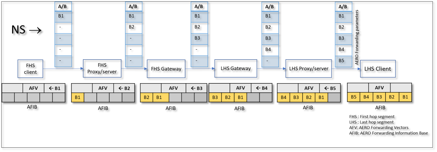
When an FHS (source) Client has packets to send to an LHS (target) Client that belong to the same OMNI link, it uses the information discovered through address resolution to dynamically establish a forwarding state based on a new concept known as ‘multilink forwarding’, which provides an OMNI Adaptation Layer (OAL) alternative to standard IP forwarding. An AERO Forwarding Information base (AFIB) is cached at every node comprising AERO Forwarding Vectors (AFVs) and AERO Forwarding Vector Indices (AFVIs). The AFVs are soft state entries that cache the full original OAL headers for future reference and are identified by 4-octet locally-unique AFVIs that are advertised to next and previous-hop nodes in the OAL forwarding path.
Following address resolution, unicast IPv6 ND NS/NA message exchanges between FHS/LHS Client peers allow all OAL nodes in the path to establish AFVs/AFVIs resulting in a consistent forwarding state in OAL source, destination, and intermediate OAL nodes. Establishing AFVs/AFVIs must be conducted on a per-interface-pair basis, since the underlay interfaces of the source and target Clients may connect through different interfaces/forwarding paths over diverse network administrative domains.
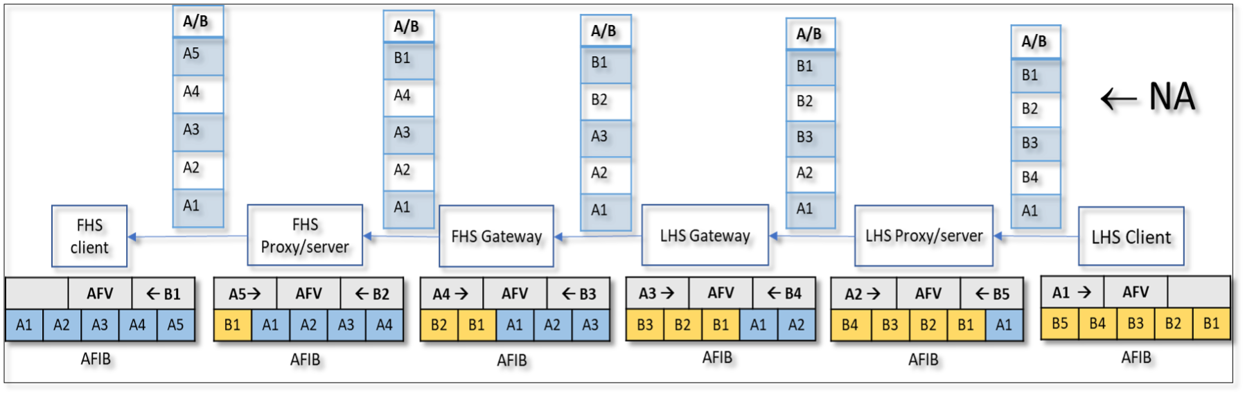
Each OAL intermediate node creates a reverse-path (‘B’) AFVI when it forwards an initiating NS message (Figure 2) and a forward-path (‘A’) AFVI when it forwards a responsive NA message (Figure 3). These ‘A/B’ AFVIs serve as locally-unique AFV identifiers corresponding to a specific FHS/LHS Client underlying interface pair. The AFIB at every FHS/LHS OAL node on the path caches the AFVIs of other OAL nodes along the path to maintain a consistent forwarding state allowing route optimization for more direct paths that bypass intermediate nodes whenever possible. Also, since the AFVIs are locally-unique and chosen from a large space, OAL nodes can easily detect and discard carrier packets with spoofed AFVIs.
OAL source nodes can forward carrier packets to the next hop while including a full OAL header containing one or more AVFIs, but this adds to the overhead in processing the packet header. The OAL nodes can therefore instead perform header compression by omitting significant portions of the OAL header to include only a single next-hop AFVI. Compressed adaptation layer headers drastically reduce the packet size without interfering with checksum calculation and verification.
Each node’s AFVs support header compression/decompression based on the context provided by its corresponding AFVIs. For example, the FHS Client’s AFV for an LHS Client is referenced by a single AFVI that provides context for next-hop forwarding and compression/decompression. Each successive OAL intermediate node then performs header compression based on the next/previous hop AFVI information and expands the full headers only when necessary for spanning tree traversal of nodes that do not cache header compression state. The compressed header follows immediately after the innermost L2 encapsulation, and the destination node can determine payload length by examining the L2 header length which is reduced by the difference in length between the OMNI Compressed Header (OCH) and full-length OAL IPv6 and fragment headers.
Header compression works in conjunction with the route optimization process
When an OAL node receives a carrier packet addressed to itself, it determines its next hop by locating the cached AFV based on the OCH AFVI. This AFV then provides addressing and AFVI context for potentially skipping unnecessary OAL intermediate hops to both reduce intermediate hop congestion and provide shorter paths to the target.
Following the initial NS/NA exchanges, the OAL peers can now exchange ordinary carrier packets through the forwarding path including all OAL intermediate nodes based on their AFIB state. Hence, the carrier packets can include only an Identification value and single-hop A/B AFVI to index each intermediate node’s AFIB while following the full spanning-tree path. The FHS/LHS Clients could then establish route optimizations to directly forward carrier packets to their local segment Gateways while bypassing their Proxy/Servers. The route optimization first requires the Clients to establish a ‘trusted’ underlay interface address to A/B AFVI mappings with the Gateways to ensure that only authorized carrier packets (and not spurious ones possibly produced by an attacker) can follow the direct path. This route optimization is provisioned to avoid congestion and overload on respective Proxy/Servers and to improve performance.
To initiate route optimization, the FHS/LHS Clients would first send NULL OAL packets known as ‘bubbles’ to update the network address translator (NAT) state for underlay interface pairs along with the local Internetwork segments to their respective Gateways path to OAL destination. Then the Client and Gateway then exchange NS/NA messages with OMNI sub-options, including interface attributes, authentication signatures and Origin Indications with the L2 data link-layer IP addresses mapped through any NATs along the path. Such message exchanges both populate the NAT state and establish a trust status for a particular underlay interface for a specific time.
The FHS/LHS Clients can then begin exchanging ordinary carrier packets via their Gateways instead of the Proxy/Servers as the next OAL hop to benefit from the route optimization. While carrier packets are still flowing, the FHS/LHS Clients are then responsible for refreshing the Gateway and NAT state by repeating the above message exchanges before timers expire so that the particular underlay interface mapping remains active and trusted. When the FHS/LHS Client peers are located on the same SRT segment, they can further proceed to establish a direct Client-to-Client communication path connection while bypassing all Proxy/Servers and Gateways following the same procedures. This may require both Clients to actively send bubbles to update the state in any NATs in the path, noting that conditions such as hairpinning through a shared NAT and symmetric NAT traversal may present challenges.
A better Internetworking experience for all
In this post, we have shown how the adaptation layer manifested by AERO and OMNI supplies missing ingredients (including Multilink forwarding, header compression, and Multilink route optimization) needed to fulfill the Catenet end-to-end and network-of-networks vision as a new path forward for Internet evolution. Adoption of an adaptation layer would therefore lead to a better Internetworking experience for all, including new service models such as pedestrian and air/ground vehicular mobile communications.
In the next post, we will discuss implications for dynamic packet size tuning within the adaptation layer and introduce an important new architectural concept known as the ‘IP Parcel’.
Contributors: Akash Agarwal, Madhuri Madhava Badgandi and Bhargava Raman Sai Prakash
Fred Templin, Akash Agarwal, Madhuri Madhava Badgandi and Bhargava Raman Sai Prakash are members of the Boeing Research & Technology (BR&T) technical staff within The Boeing Company. Their collaboration on the AERO/OMNI/DTN program since the mid-2010s has resulted in significant advancements in the technologies. They are currently engaged in producing a reference implementation for future publication.
The views expressed by the authors of this blog are their own and do not necessarily reflect the views of APNIC. Please note a Code of Conduct applies to this blog.