

This post is the fourth in a series on a new layer in the Internet architecture known as the adaptation layer. The first three posts examined the Overlay Multilink Network Interface (OMNI) and the advantages of the adaptation layer that support the ‘6 M’s of Modern Internetworking’. This post examines the inter-workings of the various layers in an integrated mobility architecture.
The Automatic Extended Route Optimization (AERO), Overlay Multilink Network Interface (OMNI) and Delay-Tolerant Networking (DTN) services together provide a multi-layered architecture to address a wide variety of mobile internetworking applications, including vehicular communications, urban air mobility and space systems.
The AERO/OMNI and DTN services establish an adaptation layer for the Internet architecture, as discussed in the previous articles of this series. Participating nodes insert the adaptation layer below the traditional network layer and above the data-link layer to satisfy the ‘6 M’ requirements. Each layer contributes an encapsulation header, and each header requires source and destination addresses taken from an address space specific to that layer.
In the AERO/OMNI architecture, the network layer uses Mobile Network Prefixes (MNPs) based on global- or private-scoped Internet Protocol (IP) prefixes (either IPv4 or IPv6) that are delegated by OMNI link ‘Proxy/Servers’ to OMNI link end systems known as ‘Clients’. These MNPs are delegated from Mobility Service Prefixes (MSPs), which are aggregated prefixes assigned to the OMNI link.
When global-scope MSPs are used, end systems on the OMNI link become addressable to correspondent nodes located on existing IPv4 or IPv6 public Internets through standard Internet routing. When private-scope MSPs are used, only communications between end systems on the same OMNI link are supported, unless the OMNI link also connects to an IPv4/IPv6 public internetwork using Network Address Translation (NAT). Most importantly, the MNPs assigned to end systems never change even if the Client corresponding to the end system moves between different underlying internetwork attachment points.
The network layer engages an OMNI interface to access the adaptation layer, which engages traditional (physical or virtual) IP network interfaces as a (pseudo) data link layer service. Each such ‘underlay’ IP network interface engages a true data link (either physical or virtual) as a lower sublayer.
The IP addresses assigned to these underlay interfaces are routable only within the scope of the connected underlying internetwork, which serves as a single segment of the (potentially) multi-segment OMNI link. They have topological relevance within the connected underlying internetwork, which must be capable of forwarding ‘carrier packets’ produced by the adaptation layer within its topological scope. Most importantly, when an end system changes to a different underlying internetwork attachment point, the IP address of the underlay interface may also need to change to provide an accurate locator at the layer below the adaptation layer.
The adaptation layer uses encapsulation and fragmentation to present MNP-addressed — IP packets produced by the network layer to the underlay IP interfaces as the (virtual) data link layer. The adaptation layer uses IP-in-IPv6 encapsulation and performs IPv6 fragmentation as necessary to present ‘carrier packets’ to underlay interfaces that are guaranteed to traverse their underlying internetworks without loss due to a size restriction. Adaptation layer ‘Gateways’ join multiple underlying internetwork ‘segments’ together to provide the network layer with the view of a single larger (bridged) virtual link. To support the traversal of this virtual link, the IPv6 header inserted by the adaptation layer requires unique addresses for which AERO/OMNI nodes use IPv6 Unique Local Addresses (ULAs).
AERO/OMNI Clients use specially formed ULAs that include their MNP as the interface identifier, while OMNI link Proxy/Servers and Gateways use ULAs with randomly generated global IDs and interface identifiers to allow for simplified OMNI link expansion and reconfiguration without requiring wide-scale renumbering. The ULAs support adaptation layer routing and forwarding so that packets can be conveyed across potentially many underlying network segments while the network layer sees only a single unified link. As for the network layer, Client ULAs do not change due to mobility. However, the mapping of Client (adaptation layer) ULAs to the changing underlay interface (data link layer) IP addresses must be dynamically updated during mobility events.
Finally, the DTN service provides a new layer above the network layer that introduces a new addressing scheme to assign Endpoint Identifiers (EIDs) to end system applications based on either a ‘dtn’ or ‘ipn’ Uniform Resource Identifier (URI) scheme. The DTN service binds the end system application EIDs to the underlying network layer MNP-based IP addresses using a convergence layer adapter. This presents the DTN layer with stable and unchanging EID-to-network-layer address bindings based purely on identity and not location, with location becoming the responsibility of lower layers.
Accommodating mobility — a new approach for mobile internetworking
Mobile Clients register their underlying interfaces with a first-hop-segment (FHS) Proxy/Server(s), which is associated with a Client-selected Hub Proxy/Server in a hub-and-spoke arrangement. Due to mobility, the IP addresses and traffic sectors of Client underlying interfaces might change. In that case, Clients are responsible to update their Hub Proxy/Server about the changes through new Router Solicitation/Advertisement (RS/RA) message exchanges using an FHS Proxy/Server in the ‘proxy’ role.
During an RS/RA message exchange, the FHS Proxy/Server assumes a hub role when the RS message is destined for its own unique local address; otherwise, it acts as a proxy. In the hub role, the Proxy/Server updates the neighbor cache entry for the Client and sends an OMNI adaptation layer (OAL) encapsulated RA message, with the source address as its own ULA, to the Client via the associated FHS Proxy/Server. In this arrangement, the Hub Proxy/Server fills the role of a mobility anchor point for the Client and advertises the Client’s MNP into the BGP routing system.
AERO/OMNI Clients and Hub Proxy/Servers include prefix delegation/registration information in their RS/RA messages. If a mobile Client’s underlying interface address changes, it sends an RS message, including this prefix information along with specific OMNI sub-options, in an RS message to update the Hub Proxy/Server through FHS Proxy/Servers accordingly. However, if the Client wishes to discontinue service with a Hub Proxy/Server, the hub processes the received information in the RS message and withdraws the Client’s MNP from the BGP routing system after a short delay. This way the distributed mobility management is maintained in the AERO system.
After the RS/RA exchanges, the Client is eligible to discover neighbors on the OMNI link by exchanging Neighbor Solicitation/Advertisement (NS/NA) messages. In the process, the Client builds up its neighbor cache based on establishing communication sessions with peer nodes (including both other Clients and Proxy/Servers acting as Relays). Thereafter, it is the Client’s responsibility to notify the updated neighbor set about any underlying interface address changes due to mobility by sending unsolicited neighbor advertisements (uNA). Hence, the Client sends an OAL encapsulated uNA with source address as its own ULA to each neighbor through the FHS Proxy/Server.
In the process, the OMNI sub-options — such as neighbor coordination, interface attributes and traffic selectors — are also modified as part of the uNA message. In particular, the interface attributes sub-option includes the updated IP address of the Client’s underlying interface, and the traffic selectors sub-option contains the updated traffic selectors if any. When the Client neighbor or a last-hop-segment (LHS) Proxy/Server associated with the Client neighbor receives the uNA, it updates the neighbor cache entry for the source Client and responds by uNA acknowledgement only if the PNG flag was set.
It is important to understand that mobility management is coordinated between the OAL and data link layers. Due to mobility events at underlying interfaces, the abstraction provided by OAL conceals the dynamically changing lower layer data-link addresses from the upper layers. Therefore, Clients can continually use fixed IP addresses at the network layer while communicating with peers, even if lower layer address mapping is changing dynamically due to mobility.
Dealing with delay and/or disruption — Delay-Tolerant Networking (DTN)
DTN is supported as a higher layer architectural overlay over the OMNI link, that is, as an ‘overlay of overlays’. A DTN path can traverse multiple OMNI links, which can each traverse multiple internetworks.
DTN has its origins in work started by NASA in 1998 for interplanetary use, where delay tolerance is the greatest need. Data transmission in DTN is done reliably even when one or more data links are subjected to long signal propagation latency or prolonged intervals of unavailability.
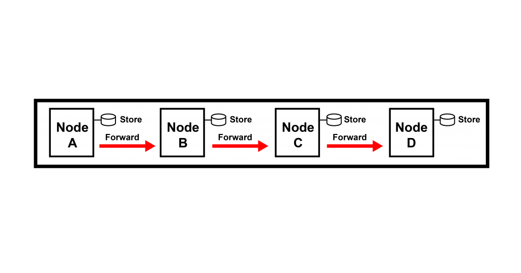
DTN uses the store, carry and forward message switching model to overcome the issues associated with sporadic connectivity, long delay and high error rates. DTN end systems and intermediate systems hold persistent storage to forward the whole message or fragments of messages from one storage place to another until it reaches its destination.
DTN uses the Bundle Protocol (BP) as its transmission protocol at the upper layers (between transport and application layers) and ties together the lower layers and application programs forming a store-carry-forward overlay network. The protocol data unit communicated by this DTN bundle protocol is called a ‘bundle’, and each bundle consists of two or more blocks of protocol data. In both space-based environments characterized by long delays and terrestrial environments characterized by frequent disruptions, effective retransmission of data is crucial.
DTN relies on the Licklider Transmission Protocol (LTP) as a convergence layer protocol layered on top of the network, adaptation and data link layers established by AERO/OMNI. The LTP lies underneath the bundle protocol and uses UDP encapsulation for transmission over the layers established by AERO/OMNI below. LTP performs automatic repeat requests (ARQ) of data transmissions soliciting selective-acknowledgement reception reports. Serving as a convergence layer protocol, LTP provides reliable communications between adjacent DTN nodes by running on top of underlying conventional Internet protocols.
The DTN LTP convergence layer has been shown to produce better performance by presenting larger blocks of data to lower layers. The AERO/OMNI ‘IP Parcels’ construct allows LTP to produce a protocol data unit containing the concatenation of up to 64 LTP segments containing BP data. Each non-final segment must be equal in length and no longer than 65,535 octets minus the length of the IP header plus extensions, while the final segment may be smaller. The DTN layer then presents the buffer and non-final segment size to lower layers that process the parcel through to the LTP peer — this may be located many AERO/OMNI internetworking hops away.
To conclude, upper-layer protocols use the DTN BP/LTP services (when necessary) as mid-layers over the network/adaptation/data link lower layers established by AERO/OMNI. This multi-layered service offers both real-time and delay-tolerant communications in conjunction with support for the ‘6 M’s’ for all internetworking applications. This natural layering construct deals with mobility at lower layers and delay/disruption at middle layers in an integrated architecture. In this way, upper layers are provided with a stable communication service with networked peers that may be located within the same or different connected internetworking regions — even between regions separated by significant delay or disruption.
Contributors: Akash Agarwal and Bhargava Raman Sai Prakash
Fred Templin, Akash Agarwal and Bhargava Raman Sai Prakash are members of the Boeing Research & Technology (BR&T) technical staff within The Boeing Company. Their collaboration on the AERO/OMNI/DTN program since the mid-2010s has resulted in significant advancements in the technologies. They are currently engaged in producing a reference implementation for future publication.
The views expressed by the authors of this blog are their own and do not necessarily reflect the views of APNIC. Please note a Code of Conduct applies to this blog.
Proud moment. Good job Dr. Akash.