

This post follows up on my previous Large Language Model (LLM) training / inference articles. Here, I delve deeper into the collective operations used in Artificial Intelligence (AI) / Machine Learning (ML) training and inference, and discuss how some of these functions can be offloaded to network switches to reduce congestion and improve the performance of the fabrics.
Using Juniper’s Trio architecture, I show how the programmable switches can handle collective offloading seamlessly. Lastly, the challenges and future trends are discussed.
This article assumes that the reader has already reviewed my other article, ‘GPU fabrics for GenAI workloads‘ so I won’t go into details of LLM training / model partitioning and so on.
What are collectives?
When computing in parallel / distributed systems with many processing nodes connected through a fabric, ‘collectives’ refer to a set of operations involving communication among a group of processing nodes (like GPUs) to perform coordinated tasks. These tasks could include distributing data from one to all group members, gathering data from all members to one, aggregating data across all members, and so on.
Deep learning frameworks support libraries that enable collective communications between GPUs in a group. For example, Nvidia Collective Communication Library (NCCL) efficiently implements the collective operations designed for their GPU architecture. When a model is partitioned across a set of GPUs, NCCL manages all communication between them.
Let’s take an example of gradient aggregation across model copies. In a GPU cluster with Nd model copies and Nm GPUs in each model copy, Nm gradient aggregation threads will run in parallel at the end of each training iteration. Each gradient aggregation thread aggregates all parameters’ gradients across all the Nm GPUs. This aggregation is a reduction operation where gradients for each parameter from all model copies are averaged to get the final gradient. The collective operation ‘AllReduce’ is used for this gradient aggregation.
Similarly, when we do parameter sharding across all GPUs in the same rank across the model copies, before each iteration, each model copy must fetch parameters from all the other GPUs in the same rank. This is done by the ‘AllGather’ collective. At the end of the training iteration, the gradients are aggregated and distributed (or scattered) across the GPUs holding respective parameters. This collective is referred to as ‘ReduceScatter’.
I’ve included a brief description of the commonly used collectives below.
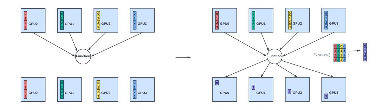
- Reduce: Aggregating (sum or average) data from all members and sending the result to one member.
- AllReduce: Aggregating data from all members and sending the result back to all the members.

- ReduceScatter: Aggregating data from all members and scatter the results (where each member gets a unique subset of the result) across all members.
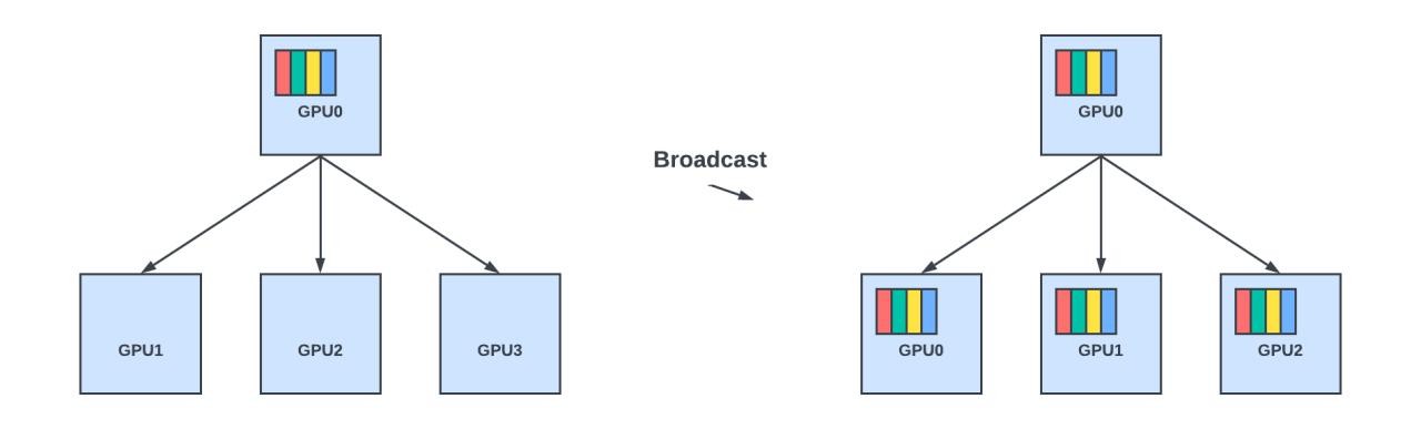
- Broadcast: Sending data from one member to all other members in the group.
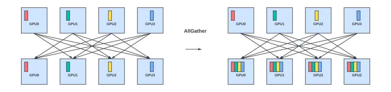
- AllGather: Gather different parts of the data and distribute it among all members.
- Scatter: Distribute different values from one member to all members.
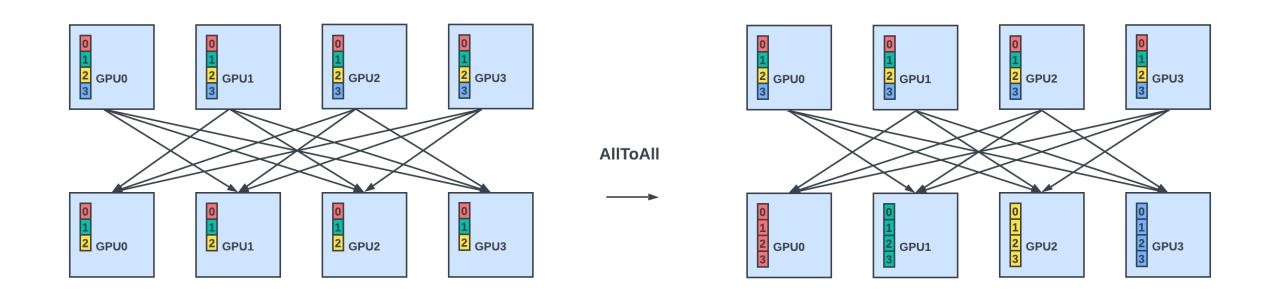
- AlltoAll: Scatter data from all members to all members
Some collectives may be implemented using a combination of collectives. For example, AllReduce can be implemented as ReduceScatter, followed by AllGather.
Collective operations in AI / ML frameworks
NCCL implements several algorithms for collective operations, such as ring, tree, and double binary trees, selecting the most efficient one based on the data size, the number of GPUs involved, and the network topology. The algorithms are designed to optimize the data transfer for collective operations.
For example, when doing gradient aggregation with the AllReduce collective operation, the gradients can be sent in a ring pattern from one GPU to the other, where each GPU aggregates the gradients it received from the previous GPU with its locally computed gradients for the parameters it holds before sending it out to the next GPU. This process is slow as gradient aggregation is done sequentially, and the final result is propagated back to all the GPUs sequentially in the ring topology.
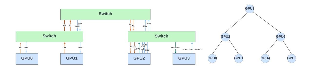
GPUs in the AllReduce collective operation can also be arranged as part of a binary tree structure. Each leaf node sends gradients for all the parameters it stores to its parent node, which is summed with the corresponding gradients from its sibling leaf node. This process continues recursively until the gradients are aggregated at the tree’s root node. After the root node has the sum of all the gradients, the aggregated gradient must be sent back to all nodes in that tree to update their local copies of the model parameters. The root node starts by sending the aggregated gradient to its children, who then pass it on to their children until all nodes have received it.
Figure 6 shows seven GPUs arranged in a binary tree for gradient aggregation. Assume these GPUs are part of a large network topology connected to different leaf and spine switches. This figure also shows the traffic patterns between the GPUs for gradient aggregation. The network switches are passive devices and switch the results between the GPUs.
In-network offloading of the collectives
What if network switches can help offload some or all of the collective operations? In this example, each switch can partially sum the gradients it receives from the GPUs belonging to an AllReduce collective operation and pass on the results to the switch in the next hierarchy. The final result could be broadcast (hierarchically) to all the GPUs for that collective.
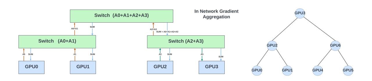
Doing so reduces the latency of this collective operation and network congestion. It also offloads the GPU computing resources for more important tasks during training. Similarly, AllGather and Broadcast are other collective operations that can benefit from off-loading in the network switches.
Nvidia supports this in their InfiniBand and NVLink switches using Scalable Hierarchical Aggregation and Reduction Protocol (SHARP). The primary goal of SHARP (version 3 is the latest) is to offload and accelerate complex collective operations directly within the network, reducing the amount of data that needs to be transferred over the network and thus decreasing the overall communication time. SHARP is a proprietary (not open-sourced) protocol that works only with Nvidia’s InfiniBand / NVLInk switches. It works seamlessly in its AI stack. Deep learning frameworks, like TensorFlow and PyTorch, often rely on MPI (message passing interface) or NCCL for collective operations. Nvidia ensures that these frameworks can utilize SHARP to get the performance advantages of in-network computation.
Nvidia didn’t publish results comparing the performance improvements with and without the SHARPv3 collectives. Some articles on older versions of SHARP show a 17-20% improvement in training performance.
Ethernet fabric and in-network collectives
When it comes to the Ethernet fabrics with ROCEv2 for GPU-to-GPU communication, there are yet to be any open standards for in-network collectives (INC). Ultra Ethernet Consortium is developing a new transport protocol (UET) and the In-Network-Collectives (INC) that go with it. This technology may be adapted by the switches and AI frameworks once the standards mature. However, there is always a lag of three to four years between any standard released and when it is deployed natively in the hardware of the network device. And it takes a couple of generations to optimize the hardware for these functions.
Doing INCs in the data plane switches requires hardware support for various operations.
- Parse new protocols / packet formats to identify if the packet is part of a collective operation.
- Able to look deeper into the packet and extract all the payload for processing.
- Able to do operations on the payload and accumulate results across several packets. This requires support for arithmetic operations in various floating-point / integer formats, which Ethernet switches usually do not implement.
- Able to read accumulated results from memory, create new packets, and send them out.
- Able to handle congestion and maintain Quality of Service (QoS) for the collection operations traffic — especially when multiple parallel collective operations are happening in the chip.
- Able to recover from errors and notify the endpoint hosts when the collective operation fails due to network or link errors or straggler GPUs.
Several approaches are available to implement the collectives. The native implementation in the switch hardware is always the most efficient. However, the standards must mature before the switches consider adding this. If these switches are for broad applications, which is always the case, this additional die area / cost could make them unattractive beyond the AI / ML applications!
The alternate option is to offload the collective operations to co-processors connected to the switches. The co-processor could contain CPU cores where collectives are implemented using software running on them. Or it could be an FPGA / ASIC with native implementations for collective processing. These co-processors usually handle a fraction of the WAN bandwidth to keep costs low. This approach keeps the Ethernet switches lean and power / cost-efficient and enables the data centres to offload collectives on some switches optionally.
The third approach is to use switches with programmable pipelines or packet processing engines, which gives the flexibility to parse new headers and payloads. Further, programmable switches allow faster implementations of new standards (as minimal or no hardware changes are needed) and could support multiple protocols that support collectives. However, these switches often have much lower (5x-10x) bandwidth, and building fabrics using these switches won’t be cost-effective for some large fabrics! However, these switches could be coprocessors for the main high-bandwidth switches to offload collectives and other processing.
In the following sections, I will use Juniper’s Trio architecture (used in MX series routers / switches) to explain how collectives can be implemented in a programmable switch with flexible packet processing engines. This is heavily based on the SIGCOMM paper MIT researchers have published in collaboration with Juniper.
In-network compute with Trio
Trio overview
Trio6 has 1.6Tbps of bandwidth. Its lookup subsystem contains many PACKET PROCESSING ENGINES (PPEs) and accelerators for specialized functions like hash / records, locks, and filters. Using high-bandwidth cross bars, PPEs communicate with the accelerators, datapath, and memory subsystem.
Each PPE is a 256-bit wide VLIW microcode engine. It has an eight-stage execution pipeline and can concurrently support multiple threads (20+). It follows a barrel pipeline architecture, where a thread can only be in a single pipeline stage at any time. This simplifies the bypasses and creates a better design optimized for area / power. PPEs are optimized for higher total throughput rather than higher single-thread performance. Each microcode instruction can control multiple ALUs, various ways of selecting operands, result routing, and complex multi-way branching, thus enabling rich packet processing functionality.
When a packet arrives, the first ~200B is sent to a free PPE thread for processing. The PPE thread can also read any additional bytes from the tail of the packet if it needs to look deeper into the packet. This feature is critical for the collective operations, as the operands (gradients, parameters) go beyond the first 200 bytes and occupy the entire packet payload.
The hash engine (accelerator) contains several hash tables where PPEs can insert, lookup, or delete entries. The hash records are stored in DataMemory and can be modified by the PPEs. It also supports aging with periodic scanning of the entries.
The memory subsystem contains DataMemory (for packet processing structures) and packet buffers for delay bandwidth buffering. A large on-chip memory fronts the DataMemory. The on-chip memory is partitioned into a memory that is an extension of the DataMemory in the address space and a large cache for DataMemory accesses. The partition between them is fungible.
Packet processing involves many read-modify-write operations. Sometimes, multiple PPEs could access the same location (for example, a counter) to update its contents. A naive approach is to give each thread complete ownership of the memory location until its read-modify-write is complete. However, this would be inefficient and could drastically decrease performance.
In Trio, PPEs offload read-modify-write operations to the memory subsystem. The memory subsystem contains multiple read-modify-write engines (each handles a specific subset of addresses) that can process these requests (eight bytes) every cycle. When multiple requests to a memory location arrive on a specific engine, the engine processes these requests in sequence, guaranteeing the consistency of the updates. There is no need for explicit coherence commands when mixing reads, writes, and read-modify-writes. The ‘modify’ operations support various bit-wise operations and two 32-bit integer additions.
The architecture also allows the creation of new packets by reading the contents of the DataMemory, attaching proper headers using PPE processing, writing the new packet to the packet buffers, and queuing them to be sent out. Thus, Trio architecture has all the hooks needed for in-network collectives.

The beauty of this architecture is that none of the processing is hardcoded in the switch. It has the flexibility to support and parse any new protocol (UEC or custom). The SIGCOMM paper uses in-network aggregation (AllReduce) to illustrate the flexibility of Trio PFEs for collectives.
In-network aggregation flow
This section describes the method used in the paper for in-network aggregation.
- First, the header (usually under the UDP layer) and packet format for collective packets need to be defined. In the SIGCOMM paper, the authors have created a custom header called the Trio-ML header. This header contains enough information to identify the aggregation thread, the source / destination GPUs, the block of gradients, and the number of gradients in the block. The ML frameworks typically allow plugins to support custom communication protocols.
- Before training starts, job records are created in the hash table by the control plane at the job configuration time and persist until the job is complete. The records contain information about all sources (GPUs) participating in the job, the number of blocks (a subset of gradients) being aggregated, and how to create the response packet (including the destination of the packet, and so on.)
- When the first packet for a job / block arrives, a block record is created in the hash table by the PPE thread. It keeps track of the status of the collective operation (in this case, gradient aggregation), including the sources from which the gradients have yet to be delivered and the pointer to the aggregation buffer in the DataMemory. The block record is removed once the block aggregation is complete.
- As the packet arrives in a PPE thread, it parses the header and looks up the job / block IDs in the hash table.
- If a block record does not exist, it creates the record and allocates an aggregation buffer in the DataMemory for this block.
- If the block record already exists, do read-modify-write to aggregate the gradients from the current packet to the aggregation buffer.
- If this is the last source from which gradients need to be aggregated (block record indicates the status of all the sources), generate the response packet, write it in the packet buffer memory, and enqueue it in the queueing subsystem. The block record is cleaned up after that.
- After the training, the system (in the control plane) can clean up the job records to free up allocated space.

The results in a small setup (with six servers of A100 GPUs and small DNN models used in image recognition) show a 1.8X performance improvement in training. This is a Proof of Concept (POC) design. While this paper specifically discusses gradient aggregation, the same workflow could support other data reduction or data gathering collective operations.
While the network switches using packet processing engines (or network processors) provide the ultimate flexibility in implementing collective operations inside the switches, these switches do not have high port densities like the shallow / deep buffer switches that use fixed pipeline packet processing. In addition, due to the limited packet processing budget, the more time spent on in-network-collectives, the less the packet processing performance (which increases the minimum packet size needed for meeting the line rate).
One way to overcome this would be to add these programmable switches as co-processors connected to the regular high-bandwidth switches and use a portion of WAN bandwidth from these switches to communicate to the co-processors for collectives.
One size does not fit all when building a fabric that enables in-network collectives with programmable switches. It depends on the cluster size, the type of models being trained, and the collectives that will be offloaded.
Other considerations for in-network-collectives
Network congestion and flow control
The existing congestion notification mechanisms can still be used to tag the result packets with Explicit Congestion Notification (ECN) marking. When the receiving host gets an ECN-marked packet generated inside the network, it knows all the source hosts involved and can revert the congestion information back to the sending hosts.
Memory requirements
The switches have limited off-chip memory. It adds additional constraints on how many collective threads can run concurrently. Further, the collectives that gather data (no reduction) could stress the memory capacity.
Spreading the collective operation across multiple switches, where each leaf switch does part of the collective operation and sends the partial results to the switches downstream (usually a spine switch), reduces the memory requirements in each switch, the network’s hot spots and evenly balances the load across the switches. In addition, by prioritizing the critical aggregation traffic and applying appropriate QoS policies, the network can ensure that critical data flows smoothly even during periods of high demand.
In addition, the endpoint hosts often only send out some data at a time to avoid overwhelming the networks and allow for scalable aggregation. Window-based approaches are common where the host sends only part of the gradients and waits for the response (either the explicit response or the implicit response where it gets the aggregated gradients from the network) before sending the new data. This also prevents buffer overflows inside the switches.
Error handling / timeouts
Suppose the network switch does not receive gradients from all the sources. In that case, it should have a timeout mechanism that would end the collective operation and either send partial results or error indications back to all source servers. In the Trio example above, this can be done by scanning the hash tables and aging the entries if they haven’t received new traffic in a predefined timeout period.
Standard programming language / interoperability
Juniper Networks’ Advanced Forwarding Interface (AFI) provides partial programmability of the device by allowing third-party developers to control and manage a section of the forwarding path graph via a small virtual container called a sandbox. The sandbox enables developers to add, remove, and change the order of operations for specific packets.
However, the broader adoption of in-network computation in network devices requires that these devices support programmable data planes compatible with the P4 programming language. Trio could support P4 primitives (it is in the works).
With P4, developers can specify how the network devices can handle packets at a very granular level, including parsing, modifying, and making forwarding decisions based on packet contents. This fine-grained control is needed to implement the various collectives inside the network. P4 also allows interoperability between different vendors. However, different vendors have different hardware architectures and behaviours, and true interoperability is hard to achieve. What compiles in P4 on one device may not be the same as on another with different hardware resources.
Security and multitenancy
Network devices can’t process data they can’t read, and network traffic is increasingly encrypted within a data centre. If the data is encrypted, there is no way to perform collective operations on the payload. While the control plane operations to set up the collectives in the switch could be secured with SSL / TLS techniques, the data plane traffic is exposed to attackers originating from within the members of the collectives.
Secure, Trusted Execution Environments (TEEs), which can be initialized and attested through other mechanisms, could mitigate the risks. One could also explore homomorphic encryption, which allows certain types of computations on ciphertext, enabling encrypted data to be processed without needing to decrypt it first. However, it is extremely expensive to implement in hardware and impractical for in-network computing applications.
The devices must strictly isolate the hardware resources for security if multiple training jobs run on the same cluster.
Despite the challenges, doing in-network-collectives in Ethernet fabric looks promising. Any improvements in job completion times and network utilization directly save millions of dollars in GPU compute resources. It is good to see UEC addressing this as a high priority with the (yet-to-be-released) INC protocol stack.
In-network collectives for inference
The usage of collectives in inference is less common than their extensive use during the training phase of deep learning models. This is primarily because inference tasks can often be executed on a single GPU. However, some LLMs require more than one GPU (especially when using mid-range GPUs) for inference with non-zero batch sizes.
However, this GPU scale is much less than required for training. When the model is partitioned across several GPUs using tensor and pipeline parallelism, the tensor parallel traffic is usually kept inside the server so that they can use the high bandwidth NVLinks. The pipeline parallel traffic uses Scatter or AlltoAll operations between the GPUs in different servers. These can be accelerated inside the network if network switches support multicast / broadcast functionalities. However, it is yet to be seen if inference workloads (especially of large language models) see significant benefits from the in-network collectives.
Other applications
In-network computing offers a promising approach to enhance edge computing. If done in network devices closer to edge devices (Internet of Things (IoT) devices), some edge computing tasks can greatly benefit from the reduced latency and bandwidth savings provided by in-network computation.
In IoT and sensor network applications, edge devices often generate vast amounts of data, which is redundant for decision making. In-network computation can aggregate and preprocess the data directly within the network, reducing the volume of data transferred to edge servers and local / cloud data centres. Processing the data generated by autonomous vehicles and data analytics are other areas of in-network computing that can help.
Programmable switches like Trio hold great promise in edge computing. They are flexible, can inspect and perform operations on the entire payload, keep state across many packets, and generate new packets — all in the data plane!
Summary
In this article, I explained the collectives used in deep learning / Generative AI (GenAI) training and how network devices can help offload them. The argument for in-networking computing has existed for over a decade and hasn’t gotten enough traction in the industry yet.
However, with the recent explosion of training workloads of large language and GenAI models and the scarcity and high cost of GPUs, any offload done in the network would translate directly into significant cost savings in public clouds and data centres.
Nvidia already supports this natively in their InfiniBand and NVLink switches. With the UEC consortium working on standardizing the INC, it is only a matter of time before these operations find their way into high-bandwidth Ethernet switches. In the meantime, programmable network devices (like Juniper’s Trio) could potentially be used standalone or as coprocessors to offload the collectives in the training workloads.
Edge computing and inference processing on edge could also benefit from the in-network offloading of data aggregation and other simple data processing operations supported by programmable network devices!
Overall, with the exponential increase of AI / Ml workloads across the spectrum, from public clouds to edge computing, switches / routers will start playing an important role in not only transmitting data as fast as they can but also in offloading some operations for improved performance and reducing costs.
Sharada Yeluri is a Senior Director of Engineering at Juniper Networks, where she is responsible for delivering the Express family of Silicon used in Juniper Networks‘ PTX series routers. She holds 12+ patents in the CPU and networking fields.
Adapted from the original at LinkedIn.
The views expressed by the authors of this blog are their own and do not necessarily reflect the views of APNIC. Please note a Code of Conduct applies to this blog.