
Previously in this series, we laid the foundation of network design for the edge and looked at various high-level edge connection examples. In this post, we will look into low-level designs, focusing on the enterprise-oriented dual single-homed setup as that will probably apply to most of the readers here. It provides just enough to cover multiple scenarios and is a proven design, but it isn’t too complex.
The edge — Layer 3
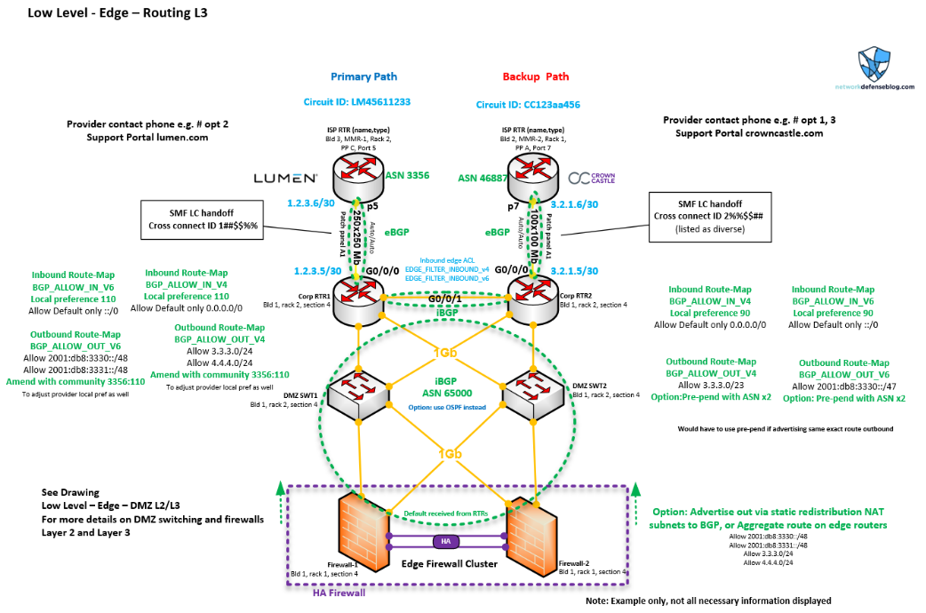
Before continuing, please look closely at all the information in Figure 1. It focuses on the final edge between our routers and the neighbouring provider’s equipment. We see some information for the Demilitarized Zone Network (DMZ) and firewalls for context, but most of the information pertains to the routers. This low-level design could really be applicable to a Service Provider (SP) or an enterprise because it has a lot of the same items each administrator would use.
You can see the circuit IDs of the primary and backup paths, cross-connect information, interfaces/ports, support information, hardware location information like the building, rack and patch panel, and device name. We see a lot of Layer 3 configuration items called out such as route-map names (including the prefixes they are covering), the access lists for filtering, IP addressing, and Border Gateway Protocol (BGP) Autonomous System Numbers (ASNs). There are also some notes on primary/backup paths and how the BGP attributes are influencing them.
These are all important items that would be covered in edge design and what I would expect to see in low-level documentation on a network diagram. Any other ideas? Let me know.
Routing
In Figure 1, we can see some information at the bottom from the firewalls, for example, using iBGP (internal) to the routers, but you could optionally use Open Shortest Path First (OSPF). We do need iBGP between the two border routers so they exchange the local preference information (only for iBGP) and will failover to the backup path when needed. And, our prefixes are still advertised to the Internet.
Think about if the edge routers receive the default route and have a local preference applied (along with the outbound advertisements). They will know which route to take outbound, but if the firewall isn’t using BGP to get those attributes then it won’t know. Therefore, if you’re using OSPF you will need to control the default route advertisement in OSPF from the edge routers to control the firewall’s routing behaviour — like a redistribution metric or E1/E2, conditional default route origination, and so on. That is why I usually would recommend BGP from the firewalls to the routers to have BGP capabilities.
One challenge noted earlier was internal to external routing. If the firewalls are running BGP to the edge, I would guess you’re probably running OSPF inside, so the firewalls would originate the default 0.0.0.0/0 or ::/0 into the inside network based on if they have the default from the border routers. However, if there are other places in that OSPF area or domain, and a default is being injected (for example, from another sister data centre (DC), there could be an administrative distance (AD) issue on those firewalls since iBGP received the default with an AD of 200, but the OSPF default is an AD of 110 or lower than iBGP and therefore chosen.
In that scenario, you’d have to block the default from the OSPF Routing Information Base (RIB) to the Forwarding Information Base (FIB) so only the iBGP default is present in the FIB. Or you could change the OSPF AD on the firewall, which is less direct in my opinion (pick your poison).
Some internal networks will be pure BGP so this wouldn’t be a problem; the routes would be carried in BGP throughout the network.
On the flip side, the advantage for an enterprise of using OSPF from the perimeter routers to the firewalls and beyond is that the default originated from the routes will be propagated into the inside network, therefore the previous example problem will not be encountered. This makes it easier for the multi-DC/Internet exit-type network.
OSPF is typically deployed in area 0, which is considered the current best practice these days. You could run an area or even a Not-So-Stubby Area (NSSA) stub that allows default injection, but I would steer away as you’d need to block the default from the FIB again on the Internet routers (assuming the NSSA default is injected from the Area Border Router (ABR) of area 0), which is less than desirable.
As mentioned, before it would probably be better to use your public IPv4 space in the DMZ for routing purposes, and if using public Network Address Translation (NAT) pools on the firewalls it will be easier for reachability, as you could just advertise those subnets via iBGP to the edge routers; with OSPF you’d likely have to redistribute a static of the NAT pools.
I usually recommend for the edge routers to be set with Next-Hop Self in the BGP configuration, so the upstream peer won’t have a next-hop issue with those NAT subnets or other downstream connected prefixes for SPs. For the IPv6 space, I would recommend carving out some DMZ networks that would only be used outside, so it’s easy to identify those areas of the network.
For larger edge Points of Presence (POPs), if not interested in running default routes only or if you have inbound services in the DMZ, doing something like partial or full route-tables from each of your providers is an option to use multiple circuits at once. This would be an active/active setup instead of having active/passive setups. You could let traffic flow in and out based on what routes are preferred from which provider on your routers. Keep in mind your hardware will need to be specified accordingly.
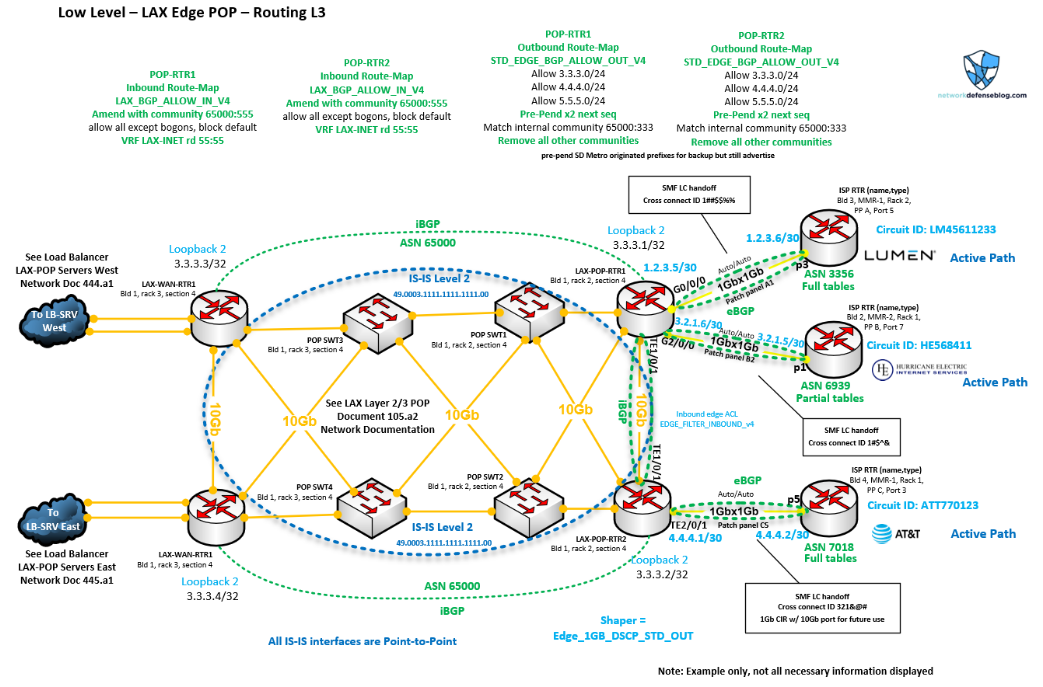
This maximizes the Return on Investment (ROI) of your circuits and technically can be set up as N+N for routers and Internet circuits for your edge. You’d get more session capacity and bandwidth from a network perspective, aside from Load Balancers (LBs) and firewalls, which also helps from a capacity perspective. Still, you’ll want to make sure your traffic flows are predictable and adjust the routing attributes accordingly.
I show a possible example of this kind of topology in Figure 2. Notice the different callouts that might be more in line with SP configurations. For example, items like BGP communities being amended or removed based on direction to allow better advertisement engineering outbound and within the domain, or running IS-IS instead of OSPF as an Interior Gateway Protocol (IGP). There might be route distinguishers for MPLS present or multi-VRF information. Despite the differences, there are still some important network edge configurations regardless of topology, like Access Control Lists (ACLs), route-maps, IP addresses, circuit IDs and Committed Information Rates (CIRs).
One side note, once you advertise your prefixes to the Internet you’ll want to check various BGP looking glasses to see if the Internet can see you, and check your ASN prepends if applicable. Don’t forget about IRR submission and RPKI review that we discussed in Part 1 [link].
If you’re using provider-assigned space, something small like a /28 then you should probably use their looking glass, as anything longer than a /24 will be aggregated beyond the ISP’s network.
BGP and route filters
If you are taking the BGP route but aren’t familiar with prefix lists and route-maps, you should definitely do some reading. It’s kind of like subnetting at first and a bit confusing but after some practice it’s easy. You could just use prefix lists for route filters in BGP, but the advantage of using route-maps is you can apply or match BGP attributes like the ones mentioned before.
Just to reiterate you primarily use short/long prefixes filtering and ASN prepending for outbound advertisements to notify the Internet how to reach you on your primary/backup pathways, and then you use BGP local preference to influence the inbound advertisements to decide the outbound flows for your inside network.
For SPs, you can also match or assign BGP communities that are vital to traffic signalling on the network. It’s important the SP admin is filtering out prefixes that shouldn’t be announced and as a safety mechanism, so a bad configuration change doesn’t incorrectly steer traffic and blackhole it!
Essentially you configure different prefixes lists with subnets to match and then assign those to different sequences in the route-map. So, for the prefix list to match the default route it would be a 0.0.0.0/0 and then for your outbound advertisements you’d list your /24 or /47 and so on. If you are receiving other routes and advertise them back you will possibly become a transit AS. Therefore, only advertise your own prefixes so you don’t receive traffic not destined for you (oops, accidental DoS).
See the Cisco syntax below for example, but the same concepts apply to most vendors.
Default only:
IPv6
RP/0/RSP0/CPU0:router(config)# ipv6 prefix-list default_only_v6
RP/0/RSP0/CPU0:router(config-ipv6_pfx)# permit ::/0
RP/0/RSP0/CPU0:router(config-ipv6_pfx)# deny ::/0 le 128
IPv4
Router(config)#ip prefix-list default_only_v4 seq 1 permit 0.0.0.0/0
Router(config)#ip prefix-list default_only_v4 seq 10 deny 0.0.0.0/0 le 32
Then, for your prefix(es):
IPv6
RP/0/RSP0/CPU0:router(config)# ipv6 prefix-list public_only_v6
RP/0/RSP0/CPU0:router(config-ipv6_pfx)# permit 2001:db8:3330::/47
RP/0/RSP0/CPU0:router(config-ipv6_pfx)# deny ::/0 le 128
IPv4
Router(config)#ip prefix-list public_only_v4 seq 1 permit 3.3.3.0/23
Router(config)#ip prefix-list public_only_v4 seq 10 deny 0.0.0.0/0 le 32
Look at adding remarks to help document the purpose of the prefix list. For SP admins you would likely have the customer or peer prefixes instead of the default-only prefix in inbound filtering. This is important to avoid propagating bad route advertisements. Use show commands to verify your configuration.
Next, you need to match those prefix lists in route-maps. We’ll use the IPv4 example —primary router for primary path, no prepend and preferred local preference:
Router(config)#route-map BGP_ALLOW_IN_v4 permit 10
Router(config)#description for inbound BGP received routes
Router(config)# match ip address prefix-list default_only_v4
Router(config)#set local-preference 110
!remember we need to set the local preference preferred for router 1
Router(config)#route-map BGP_ALLOW_IN_v4 deny 50
!
Router(config)#route-map BGP_ALLOW_OUT_v4 permit 10
Router(config)#description for outbound BGP advertisements
Router(config)#match ip address prefix-list public_only_v4
!we only want to advertise OUR prefix(es) only, nothing else
Router(config)#set community 3356:110
!setting BGP community based on provider information for local preference
Router(config)#route-map BGP_ALLOW_OUT_v4 deny 50
!
end
For the secondary router for the backup path, we’ll need to prepend and have a lower local preference:
Router(config)#route-map BGP_ALLOW_IN_v4 permit 10
Router(config)#description for inbound BGP received routes
Router(config)# match ip address prefix-list default_only_v4
Router(config)#set local-preference 90
!remember we need to set the local preference less for router 2
Router(config)#route-map BGP_ALLOW_IN_v4 deny 50
!
Router(config)#route-map BGP_ALLOW_OUT_v4 permit 10
Router(config)#description for outbound BGP advertisements
Router(config)#match ip address prefix-list public_only_v4
!we only want to advertise OUR prefix(es) only, nothing else
Router(config)#set as-path prepend 65000 65000
!this will add 2 ASNs to the path thereby making it less preferred
Router(config)#route-map BGP_ALLOW_OUT_v4 deny 50
!
end
This is helpful because the route-map is applied in the configuration, so editing the prefix list is simpler if things are structured well.
Next, we tie it all together in our BGP configuration, using the Cisco syntax below for router one, but similar concepts are also handled the same with other vendors. I’ve left out the iBGP configuration to router two and the firewalls from the low-level design, only looking at the ISP neighbor and am using the old BGP syntax, for example, purposes only.
Router(config)#ip bgp-community new-format
Router(config)#router bgp 65000
!for big routers don't forget nsf or nsr etc.
Router(config)#bgp router-id 3.3.3.1
Router(config)#bgp log-neighbor-changes
Router(config)#network 3.3.3.0 mask 255.255.252.0
!if you have that route present or a static null0 then can use network cmd
!next the neighbor
Router(config)#neighbor 1.2.3.6 remote-as 3356
Router(config)#neighbor 1.2.3.6 description primary DIA
Router(config)#neighbor 1.2.3.6 password pasw0rd123
Router(config)#neighbor 1.2.3.6 soft-reconfiguration inbound
Router(config)#neighbor 1.2.3.6 send-community both
Router(config)#neighbor 1.2.3.6 next-hop-self
Router(config)#neighbor 1.2.3.6 route-map BGP_ALLOW_IN_v4 in
Router(config)#neighbor 1.2.3.6 route-map BGP_ALLOW_OUT_v4 out
!
end
Use show commands to verify your configuration. There are other knobs like route policies and communities that can be used to aggregate and streamline configurations and filtering but that is beyond the depth of this post. More links about prefix lists and route-maps are listed at the end of the post.
Edge filtering
If you recall from the diagram there is a call out for an ACL called EDGE_FILTER_INBOUND. One advantage of using perimeter routers before the firewall and presumable DMZ devices is that you can filter attack and BOGON traffic as it’s called before it hits the firewall or the rest of the network. This can be a good screening process where you can block some large adversary subnets, unused subnets, and also ports for common attack traffic like DDOS amplification, which can save resources on the firewall or other devices.
I list some articles to research at the end of this post. You’ll want to research as to what this ACL should contain and remember it’s placed inbound on your outside interface, so don’t forget to allow exiting traffic back in!
All SPs should also block BOGONs as a best current practice along with their own prefixes inbound usually on peering connections to avoid spoofing or loops. SPs should also block common Distributed Denial-of-Service (DDoS) amplification ports (in my opinion), so the edge ACL can apply to both providers and enterprises. If you’re an SP admin and aren’t doing this but are considering it, let me know what you come up with.
Below is an IPv4 Cisco syntax ACL example:
Router(config)#ip access-list extended EDGE_FILTER_INBOUND_V4
remark ingress filtering on border router to dmz
permit ip host 1.2.3.5 host 1.2.3.6
permit ip host 1.2.3.6 host 1.2.3.5
permit icmp any 3.3.3.1 0.0.0.0
permit icmp any 3.3.3.2 0.0.0.0
deny ip any 3.3.3.192 0.0.0.248
deny   pim any any
deny   udp any any eq 1433
deny   udp any any eq 3389
deny   tcp any any eq 3389
deny   tcp any any eq 1433
deny   udp any any eq 10074
deny   udp any any eq 445
deny   tcp any any eq 445
deny   udp any any eq 4444
deny   tcp any any eq 4444
deny   udp any any eq 27960
deny   udp any any eq 11211
deny   tcp any any eq 11211
deny   udp any any eq 3702
deny   tcp any any eq 3702
deny   ip 0.0.0.0 0.255.255.255 any
deny   ip 10.0.0.0 0.255.255.255 any
deny   ip 100.64.0.0 0.63.255.255 any
deny   ip 127.0.0.0 0.255.255.255 any
deny   ip 169.254.0.0 0.0.255.255 any
deny   ip 172.16.0.0 0.15.255.255 any
deny   ip 192.168.0.0 0.0.255.255 any
deny   ip 198.18.0.0 0.1.255.255 any
deny   ip 224.0.0.0 15.255.255.255 any
deny   ip 240.0.0.0 7.255.255.255 any
deny   ip 248.0.0.0 7.255.255.255 any
deny   ip host 255.255.255.255 any
deny   ip 3.3.3.0 0.0.0.252 any
!you could have a permit IP any any or you can have it with these and then a deny IP any any, depends on the goals and SP vs enterprise use cases
permit udp any any eq 30000 50000
permit udp any any eq 4500
permit udp any any eq 500
permit tcp any any established
deny ip any any
The DMZ — Layer 2 and 3
In this last section, we will examine the low-level design section in the DMZ. This is where the border routers will connect to the edge firewalls or load balancers that provide protection to the internal network.
We can see more detail on the switches and firewall versus our other edge Layer 3 diagram from Figure 1 as far as what interfaces are involved, specific IP addresses, spanning-tree, and port-channel information.
Also, notice the specific callouts to reference other diagrams for information. Perhaps you’d have a detailed diagram for the Virtual Port Channel (VPC) of the two switches, and also a detailed diagram of the core network to the firewalls before it reaches the DMZ showcasing those interfaces and OSPF as discussed earlier.
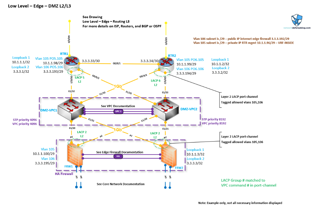
We can see the DMZ VLANs for connectivity and what IP addresses are being used for what purposes. We can see for the routers there is internal management via Virtual Routing and Forwarding (VRF). This is a common best practice for the outside zone in order to keep your outside traffic totally segmented logically from a Layer 2 (VLAN) and Layer 3 (VRF) perspective. You’d then build this down to your firewalls where you’d have a special zone for outside untrusted management. SPs probably all have multiple VRFs for customers and different services, but I know some don’t have VRF segmentation for management as well!
We see that the DMZ switches are logically connected via VPC for high availability (you could also use stacking, or chassis with separate line cards), which allows for Link Aggregation Control Protocol (LACP) port channels to be used between the two routers and High Availability (HA) firewalls to the switches — adding more resiliency in case an interface or optic fails. Plus, with port channels, you can remove or add interfaces without impacting anything, which is good for maintenance.
Speaking of maintenance, having an edge setup like this makes it easy for maintenance, since you can steer traffic with the two perimeter routers based on which one is getting rebooted or changed.
We can see what specific ports are listed here so when we go to connect all the devices or need to troubleshoot something we have a detailed as-built document. Moreover, Figure 3 shows the detail we need to prove that there is a clear delineation between the inside and outside networks.
I like having inside management and outside management loopbacks; these will often be the BGP or OSPF router IDs and can be endpoint IPs to test connectivity and so forth.
Maybe to make this diagram a little better I might list more firewall-related information like NAT subnets, zones, make/model, and so on, and more VLAN information if there were DMZ services running in this outside network. We could also show standard interface configurations for those outside interfaces — this would also be important for when DMZ switches are doing double duty as functionally inside network switches.
Conclusion
Throughout this series, we’ve covered many aspects of the network edge from connecting to your SP (or other providers) and having adequate diversity, to the challenges of routing in and out of the network. We looked at different high-level designs being single or dual-homed, using BGP or PING for path control and covered low-level analysis of the DMZ and Layer 3 routers at the perimeter. We covered detailed configurations from prefix lists to access-control traffic filters, along with the importance of filtering for BGP and applying attributes for route control.
For both SPs and enterprises, the need to connect to outside networks and for those networks to connect back will be as important in the future as it is now. We want to route, filter, and design our network edges properly for our business needs and I hope this post helps you do that. Thanks for reading.
Would you like to learn more?
- Network Ingress Filtering
- BOGON Ingress Filtering example
- Juniper Solution Documentation
- Cisco BGP Guide
- Juniper BGP Guide
- Fortinet BGP Guide
- Palo Alto BGP Guide
- Arista BGP peering examples for enterprises
- Cisco Prefix lists
- Cisco Route-Maps
- Cisco BGP Communities
- Juniper Route Policies
- Juniper Route filtering
- DMZ Design
Brandon Hitzel (Twitter) is a network engineer who has worked in multiple industries for a number of years. He holds multiple networking and security certifications and enjoys writing about networking, cyber defence, and other related topics on his blog.
This post is adapted from the original at Network Defense Blog.
The views expressed by the authors of this blog are their own and do not necessarily reflect the views of APNIC. Please note a Code of Conduct applies to this blog.