

In this post, I will introduce Topology Independent – Loop-Free Alternates (TI-LFA) — a fast-reroute (FRR) mechanism that leverages Segment Routing (SR). (See my previous post on how a network operator can use SR to implement the traffic engineering policy.)
To understand TI-LFA, lets first understand its predecessors, Loop-Free Alternates (LFA) and Remote Loop-Free Alternates (RLFA).
Loop-Free Alternates (LFA)
In Figure 1, R1 calculates its least-cost route to R6. This least-cost route traverses Link R1->R2. R1 forwards traffic destined for R6 through Link R1->R2.

Without LFA, when Link R1->R2 fails, R1 discards traffic destined for R6. This condition persists for milliseconds, seconds or even tens of seconds, while R1 calculates and installs a new route to R6. From the time that Link R1->R2 fails until R1 installs a new route to R6, R1 is in a pre-convergence state regarding R6. When R1 installs the new route to R6, it enters a post-convergence state regarding R6.
When LFA protects Link R1->R2, R1 executes the following procedure:
- Calculate the least-cost route to R6 (that is, via Link R1->R2).
- Identify a node that provides an LFA (that is, R3).
- Identify a repair path to that node (that is, Link R1->R3).
When Link R1->R2 fails, R1 forwards traffic destined for R6 through the repair path (that is, Link R1->R3). R3 forwards this traffic towards R6 through Link R3->R5. Connectivity is preserved while R1 calculates and installs a new route to R6. During this convergence period, R1 serves as the Point of Local Repair (PLR) while R3 serves as the repairing node.
In the example above, R3 provides an LFA to R6 because it satisfies the following criteria:
- The loop-free criterion (that is, when R3 is in its pre-convergence state, its least-cost path to R6 does not traverse R1).
- The downstream criterion (that is, when R3 is in its pre-convergence state, the total cost from R3 to R6 is less than the total cost from R1 to R6).
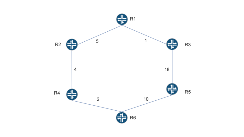
LFA repair paths are not available in all network topologies. Figure 2 is identical to Figure 1, except for one detail. The metric associated with Link R3->R5 is 18.
In this topology, R1 calculates its least-cost route to R6. This least-cost route traverses Link R1->R2. However, when LFA attempts to protect Link R1->R2, R1 cannot identify a repair path to R6.
R3 does not offer an LFA to R6 because it does not satisfy the loop-free criterion. When R3 is in its pre-convergence state, its least-cost path to R6 traverses R1. If R1 were to send traffic destined for R6 through Link R1->R3, R3 would send that traffic back to R1.
From this example, we observe the following regarding LFA:
- The repair node must be a neighbor to the PLR.
- The repair node must satisfy the loop-free and downstream criteria.
- In many network topologies, the PLR does not have a neighbor that satisfies these criteria.
- In many network topologies, repair paths may not be available for all downstream nodes.
Remote Loop-Free Alternates
RLFA addresses LFA limitations by allowing selected nodes to serve as repair nodes, even if they are not neighbors to the PLR.
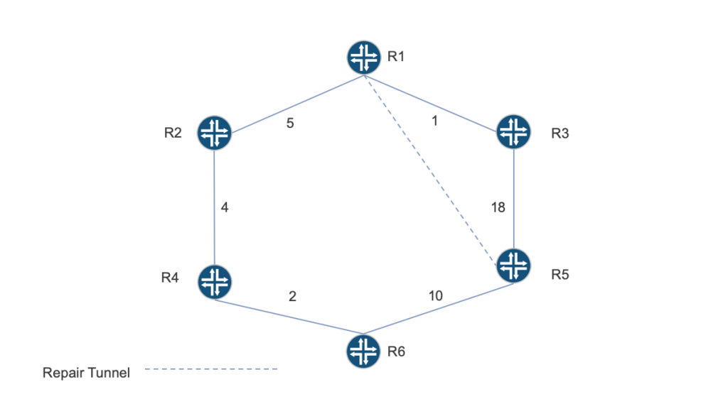
In Figure 3, RLFA protects Link R1->R2. R1 executes the following procedure:
- Calculate the least-cost route from R1 to R6. This least-cost route traverses Link R1->R2.
- Identify R1’s P-space regarding Link R1->R2. R1’s P-space contains nodes that R1 can reach, in its pre-convergence state, without traversing Link R1->R2. Nodes R3 and R5 are in R1’s P-space.
- Identify R6’s Q-space regarding Link R1->R2. R6’s Q-space contains nodes that can reach R6, in their pre-convergence state, without traversing Link R1->R2. Nodes R2, R4, R5 and R6 are in R6’s Q-space.
- Identify R1’s PQ-space regarding R6 and Link R1->R2. R1’s PQ-space is the intersection of its own P-space and R6’s Q-space. Only R5 is in the PQ-space.
- Select a repair node from PQ-space. In this example, R5 is the only candidate for selection.
- Create a repair tunnel from the PLR (that is, R1) to the repair node (that is, R5). The repair tunnel traverses the least-cost path from the PLR to the repair node. It can be a Label Distribution Protocol-signalled Multiprotocol Label Switching (MPLS) Label Switched Path (LSP) or an SR path that contains a single node segment, ending on R5.
If Link R1->R2 fails, R1 forwards traffic destined for R6 through the repair tunnel. R5 decapsulates tunnel payload and forwards it to R6. Thus, connectivity is preserved during the convergence period.
While RLFA protects some topologies where LFA does not, RLFA does not protect all network topologies. The topology depicted in Figure 4 is identical to the topology depicted in Figure 3, except for one detail. The metric associated with Link R3->R5 is 22.

In this topology, R1’s P-space regarding Link R1->R2 includes only R3. R6’s Q-space regarding Link R1->R2 includes R2, R4, and R5. Therefore, R1’s PQ-space regarding R6 and Link R1->R2 is empty. No repair nodes are available.
From this example, we observe the following regarding RLFA:
- Because repair tunnels rely on least-cost forwarding, the repair node must be in the PLR’s P-space.
- Because packets are forwarded along the least-cost path from the repair node to the destination, the repair node must be in the destination node’s Q-space.
- In many network topologies, the intersection of P-space and Q-space (that is, PQ-space) is empty.
- In many network topologies, RLFA repair paths are not available for all downstream nodes.
Topology Independent – Loop-Free Alternates
Topology Independent – Loop-Free Alternates (TI-LFA) addresses RLFA limitations by using SR paths as repair tunnels.
Because the repair tunnel is an SR path, it is not required to traverse the least-cost path between the PLR and the repair node. It can traverse any viable path specified by the PLR. Thus, the repair node can be outside of the PLR’s P-space. However, the repair node must be within the destination node’s Q-space. Sometimes, the repair node is also the destination node.
Like RLFA, TI-LFA offers link and node protection. Each is described below.
TI-LFA link protection
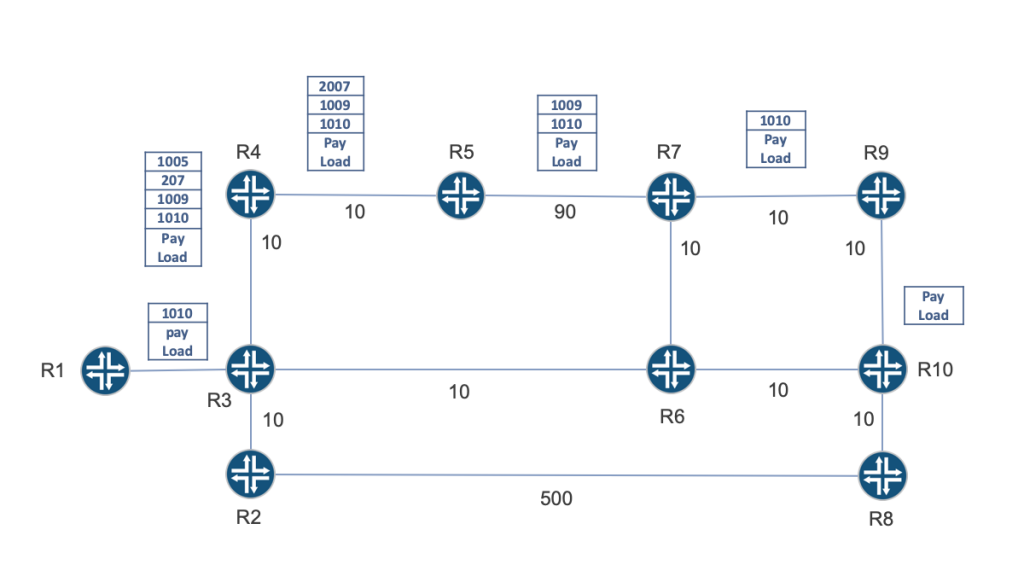
In Figure 5, assume:
- A node segment ends on R10. Every node in the figure associates MPLS label 1010 with that node segment.
- TI-LFA protects Link R3->R6.

Here, R3 executes the following procedure:
- Calculate the least-cost route to R10. This least-cost route traverses Link R3->R6.
- Calculate the post-convergence path to R10.
- Construct and install a repair tunnel.
The post-convergence topology excludes the failed link (that is, Link R3->R6). The post-convergence path to R10 contains:
- Link R3->R4.
- Link R4->R5.
- Link R5->R7.
- An Equal Cost Multipath (ECMP) between R7 and R10. One member of this ECMP traverses Link R7->R6 while the other ECMP member traverses Link R7->R9.
The repair tunnel is defined by an outgoing interface on R3 (that is, R3->R4) and a repair list. The repair list contains:
- A node segment that ends on R5, represented by MPLS label 1005.
- An adjacency segment that ends on R7, represented by MPLS label 207. This adjacency segment forces the packet to traverse Link R5->R7, even though IGP metrics would not cause the packet to traverse that link.
Because the repair tunnel ends on R7, R7 serves as the repair node.
If Link R3->R6 fails, R3 forwards traffic destined for R10 through the repair tunnel to R7. R7 is within R10’s Q-space. Traffic released from the repair tunnel is then forwarded to R10, regardless of whether the intermediate nodes, R6 and R9, are in pre-convergence or post-convergence states regarding R10.
R7 distributes traffic between the two ECMP members and connectivity is preserved during the convergence period.
TI-LFA node protection
TI-LFA can also protect against node failures. In Figure 6, assume:
- A node segment ends on R10. Every node in the figure associates MPLS label 1010 with that node segment.
- TI-LFA protects Node R6.
Because TI-LFA protects Node R6, all of R6’s neighbors treat all links connected to R6 as members of a Shared Risk Link Group (SRLG). For example, if R3 detects the failure of Link R3->R6, it behaves as if Links R7->R6 and R10->R6 also failed. The following paragraphs show this concept.
When TI-LFA protects R6, R3 executes the following procedure:
- Calculate the least-cost route to R10. This least-cost route traverses Link R3->R6.
- Calculate the post-convergence path to R10.
- Construct and install a repair tunnel.
The post-convergence topology excludes the failed link (that is, Link R3->R6). It also excludes Link R7->R6 and Link R10->R6 because they are part of the SRLG. As a result, the post-convergence path to R10 contains:
- Link R3->R4.
- Link R4->R5.
- Link R5->R7.
- Link R7->R9.
The repair tunnel is defined by an outgoing interface on R3 (that is, R3->R4) and a repair list. The repair list contains:
- A node segment that ends on R5, represented by MPLS label 1005.
- An adjacency segment that ends on R7, represented by MPLS label 207.
- A node segment that ends on R9, represented by MPLS label 1009.
The repair tunnel avoids R6 and all its links. Because it ends on R9, it also avoids one of the ECMP members that connect R7 to R10. This ECMP member is avoided because it traverses R6.
If Link R3->R6 fails, R3 forwards traffic destined for R10 through the repair tunnel to R9. R9 decapsulates tunnel payload and forwards it through Link R9->R10, preserving connectivity during the convergence period.
TI-LFA provides 100% coverage
TI-LFA is a simple FRR mechanism that can protect all nodes and all links in all network topologies. For this reason, we say that TI-LFA provides 100% coverage.
TI-LFA motivates many network operators to deploy SR. These operators want their traffic to traverse the least-cost path from source to destination but require FRR in topologies that LFA and RLFA cannot support.
Watch a recording of Ron’s presentation on the Evolution TI-LFA at NANOG 79 (slides).
Adapted from original post which appeared on the Juniper Blog.
Ron Bonica is a Distinguished Engineer at Juniper Networks, specializing in IPv6 and Segment Routing.
The views expressed by the authors of this blog are their own and do not necessarily reflect the views of APNIC. Please note a Code of Conduct applies to this blog.
Very Nicely Explained
Well explained Ron