

Network slicing is a term (and a concept) that has entered the lexicon of the networking/communications industry in the last few years. It is a capability that has been defined by The 3rd Generation Partnership Project (3GPP) in the context of 5G technology.
Before delving deeper into the concept of network slicing, it may be useful to recap the primary use cases that 5G is designed to address.
5G use cases
There are three basic use cases that 3GPP, the prime body for mobile specifications development, is working towards:
- Enhanced Mobile Broadband (eMBB): This use case is focused primarily on higher bandwidth.
- Massive Machine-Type Communication (mMTC): This is focused on Internet of Things (IoT) applications, where the key requirements are to support a large number of low-cost endpoints and lower battery life.
- Critical Machine-Type Communication (cMTC): This is focused on critical industrial IoT applications that demand ultra-high reliability and low latency.
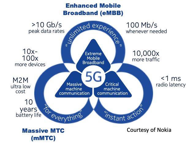
As shown in Figure 1, these three use cases require potentially conflicting network capabilities. 5G networks will have to simultaneously support a variety of diverse and extreme requirements for latency, throughput, capacity, and availability, and need to be carefully architected to provide an optimal balance between service capabilities and network investment. Operators will also be expected to commit to specific Service Level Objectives (SLOs) to achieve either their business objectives or to comply with the contracted capabilities of each use case. This is where network slicing comes in.
Defining network slicing
3GPP defines a network slice as:
‘A logical network that provides specific network capabilities and network characteristics’ and a network slice instance as ‘A set of Network Function instances and the required resources (for example, compute, storage and networking resources) which form a deployed Network Slice’.
3GPP TS 23.501 V16.7.0 (2020-12)
Network slicing ideally enables the dynamic creation of logical networks within the same physical network supporting different use cases, traffic loads, and end user communities. It extends from the user device through the Access Network (AN), Transport Network (TN) and Core Network (CN). See Figure 2 for an illustration of these network components and an accompanying explanation. It is important to appreciate that a network slice is an end-to-end concept constructed across the various networks it traverses.
The end-to-end slice delivers the appropriate isolation, resources, and optimized virtual network architecture to serve specific use cases, SLO requirements, or business solutions.
Network slices are orchestrated to form service-specific logical networks running on the same physical network that meet certain service attributes such as data speed, capacity, latency, reliability, availability, coverage, and security.
Network slicing offers an effective way to meet diverse use case requirements and exploit the benefits of a common network infrastructure. It enables operators to establish different capabilities, deployments, and architectural flavours, for each use case or service group and run multiple network instances in parallel.
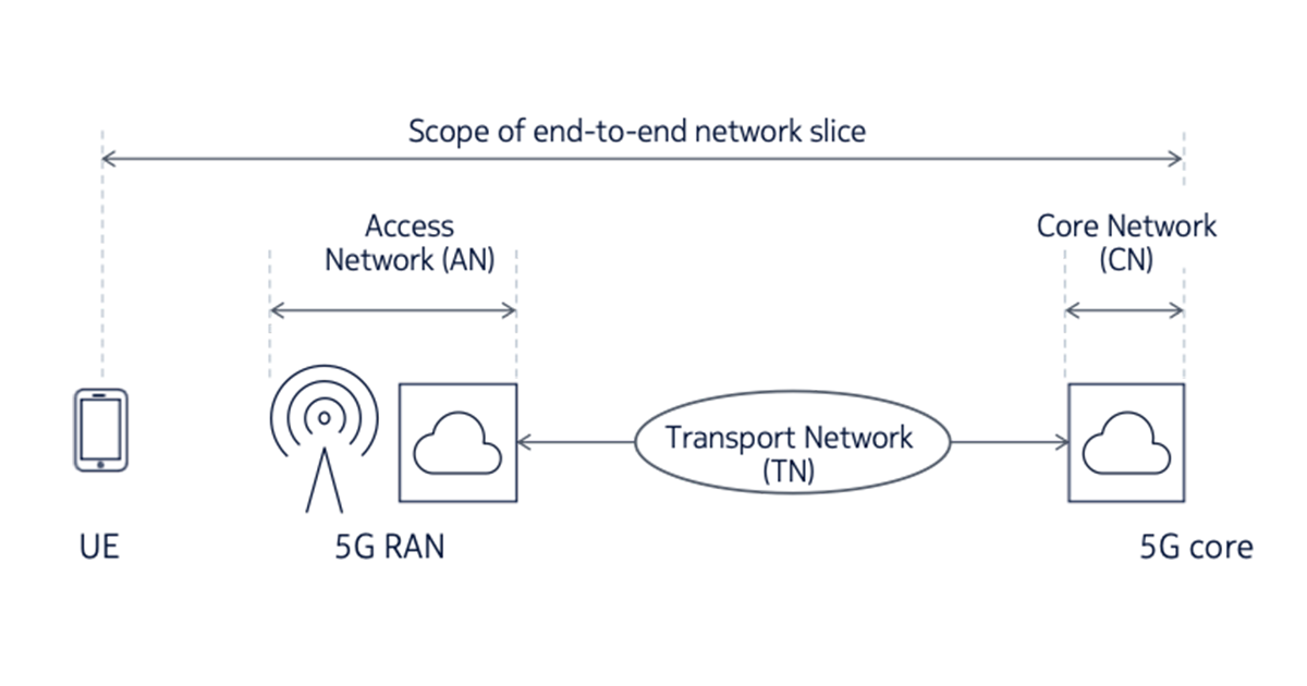
- User Equipment (UE): The end-user terminals that interface to the mobile network over the ‘air interface’. These include mobile handsets, data modems and tablets.
- Access Network (AN): The set of elements that make up the Radio Access Network (RAN), including the base station, antennas and spectrum resources.
- In the case of a disaggregated RAN, it also includes elements such as the Radio Unit (RU), Distributed Unit (DU) and the Centralized Unit (CU). Figure 2 is a simplification and does not show all of the possible Radio Access Network (RAN) functional splits.
- Core Network (CN): A set of functions that includes signalling, authentication, subscriber management, mobility, interfaces to external network and other control-plane and management-plane services. The 5G core may be distributed at various points within the network. The above diagram is a simplification to show a centralized deployment of the 5G core.
- Transport Network (TN): The transport network that is used to carry traffic between the AN and the CN. In the case of a disaggregated RAN architecture, there would also be instances of the TN inter-connecting the RAN components such as the RU, DU and CU.
Standardization
3GPP has defined the essential elements of 5G network slicing, particularly in the RAN and core domains. The standardization of other aspects of network slicing is an ongoing activity. There are active efforts in standardization bodies to develop technologies to implement elements of network slicing such as transport slicing. In this post, we focus on technologies being defined mainly by the Internet Engineering Task Force (IETF).
Examples of network slicing use cases
Example 1: An automated vehicle slice requires the end-to-end network to deliver capabilities such as data rate, reliability, latency, communication range, and speed for the specific slice instance serving the use case within the network.
Example 2: An IoT slice serving applications such as smart metering or wearable medical device will require the network to support a large number of low-latency and high-density IoT devices securely, efficiently, and cost-effectively.
Implementing network slices
As discussed above, 5G network slicing can be used to ensure that end-to-end performance, as well as service and application requirements, meet customer expectations. To implement network slicing, the individual network segments (access network, transport network and core network) must be examined as a whole. The lifecycle of network slices needs to be orchestrated across the entire network.
Figure 3 illustrates the key elements involved in the implementation of an end-to-end slice. This particular network offers network slicing services to three customers, depicted as tenants A, B, and C.
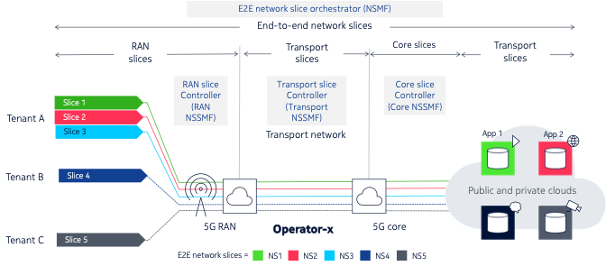
Tenant A has three different slices, while tenants B and C have one slice each. Each slice is constructed as an end-to-end network slice comprised of several sub-slices:
- A RAN (sub) slice
- A transport (sub) slice connecting the RAN slice to the core slice
- A core (sub) slice
- A second transport (sub) slice connecting elements within the core network
Each of the slices above is lifecycle-managed by a domain-specific orchestrator/controller, called the Network Slice Subnet Management Function (NSSMF) in 3GPP parlance:
- The RAN slice is managed by the RAN controller or RAN NSSMF.
- The transport slice is managed by the transport slice controller or transport NSSMF.
- The core slice is managed by the core controller or core NSSMF.
The NSSMFs have domain-specific knowledge that is required to realize the sub-slice in that domain. The NSSMF is responsible for:
- Creating the slice
- Maintaining the slice
- Terminating the slice when no longer required
- Implementing a north-bound interface that exposes an abstracted view of the domain and allows the slice to be consumed by the NSMF (see below)
The highest level of this hierarchy contains an end-to-end network slice orchestrator, or more precisely in 3GPP terminology, the Network Slice Management Function (NSMF). The NSMF has the function of stitching together the sub-slices to create the end-to-end slice. The NSMF communicates with the NSSMFs via their northbound interfaces to do so. It also, in turn, exposes an abstracted northbound interface to allow its services to be consumed to create end-to-end slices.
Realizing network slices
Each of the domain-specific sub-slices allocates or provisions one or more of the following resource types depending on the nature of the slice or sub-slice:
- Virtual and physical network functions
- Spectrum
- Bandwidth
- Transport-layer connectivity model
- Augmented services (for example, network analytics and security services)
- Quality of Service (QoS) profile
- Application functions
For example, a RAN slice may include mechanisms to share spectrum resources between all the slices sharing the air interface. On the other hand, a core slice may assign dedicated compute resources for signalling traffic. A transport slice may use mechanisms to apportion network capacity to each slice.
Hard and soft slicing
The level of sharing of network resources — hard and soft slicing — depends on the service level objective associated with the network capability. The key difference between ‘hard slicing’ and ‘soft slicing’ is that hard slicing results in network resources being dedicated to a slice whereas soft slicing allows the use of shared resources.
The allocation of dedicated, non-shared resources to each network slice instance guarantees the performance, availability, and reliability required for each application or customer. Conversely, these resources cannot be used for other slices in case they are not fully used. Therefore, hard slicing may not be very cost-efficient.
Soft slicing allows for a controlled overbooking of transport resources, which results in more economical use of network resources for high-volume applications with more relaxed constraints.
It may be argued that soft slicing should be used by default unless a service level objective requires hard slicing.
Transport slices
The earlier part of this post introduced end-to-end slicing, its definition, and how it can be implemented. The remainder of the post focuses on transport-layer slicing and how it can be realized.
A transport slice can be defined as a distinct set of connections between Physical Network Functions (PNFs) and Virtual Network Functions (VNFs). Such transport slices have deterministic SLAs to achieve the end-to-end SLO for the complete end-to-end network slice. These SLOs include parameters such as QoS, availability, latency and packet loss.
Transport slices can be realized:
- Through multiple technology types (IP/MPLS, optics, microwave, PON)
- Through multiple tunnel types (wavelengths, ODU, VLANs, IP/MPLS VPNs, segment routing)
- At layers zero to three
IP and optical transport networks have been used to deliver virtual networks using various network virtualization techniques for many years. What exactly, then, is new when it comes to transport slices? The key new requirements for transport networks are:
- The association of new SLO types, such as latency, that have previously not been a stringent requirement. In addition, there is a need to ensure compliance with the SLO over the lifetime of the service and not just during initial provisioning.
- Data-plane technologies that can scale to support fine-grained traffic engineering, potentially on a per-flow basis.
- Near-real-time visibility of network state and performance using streaming telemetry.
- Enhanced network programmability using model-driven approaches, for example, YANG models.
- The need for centralized path computation, which in turn, requires new mechanisms for network visibility.
- A closed feedback loop between the network and the control systems.
- An abstracted API that allows the transport controller (NSSMF) to communicate with the end-to-end orchestrator (NSMF).
There are several requirements that IP transport slices must satisfy to meet the SLAs of the end-to-end network slice — Table 1 outlines some of these and their necessity.
| IP slice requirement | Motivation |
| Virtual network connectivity | To provide isolation between multiple tenants and slices sharing the same physical underlay |
| Flow-based traffic engineering | To allow fine-grained SLO requirements to be fulfilled |
| Bandwidth guarantee | To support applications that require a uniform level of capacity through the network |
| Latency guarantee | To support applications that tolerate a specified maximum latency |
| Availability guarantee | To support applications that need to be highly available |
| QoS within slice | To allow differentiation within each slice |
| Lifecycle management | To be able to create, modify and release slices on an on-demand basis |
Table 2 presents a non-exhaustive set of candidate technology solutions to deliver the requirements highlighted in Table 1.
| IP slice requirement | Candidate solutions |
| Virtual network connectivity |
|
| Flow-based traffic engineering |
|
| Bandwidth/latency/availability guarantee |
|
| Lifecycle management |
|
| QoS within slice |
|
Table 2’s set of capabilities can be combined to build a transport network that forms a closed loop with a central controller, as shown in Figure 4.
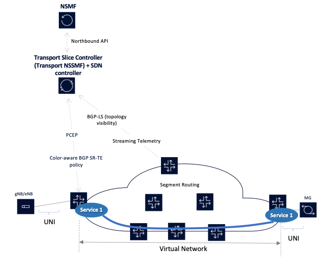
In this example, a closed feedback loop exists between the network implementing the data plane of the transport slice and the controllers managing and/or orchestrating the network. In this network:
- A service is required between the base station (gNB/eNB) and the mobile gateway (MG).
- The service has certain SLOs that it requires, for example, a maximum latency bound.
- There is a controller that is functioning both as an SDN controller and a transport NSSMF.
- The network exposes its topology to the controller via BGP-LS.
- The network also streams telemetry information to the controller so that it has an up-to-date understanding of the network. The telemetry information includes link utilization and latency, among other things.
- The controller uses its path computation engine to compute a path between the edge routers that connect to the gNB/eNB and the MG.
- The controller conveys the computed path information to the edge routers using either PCE or BGP SR-policy; the edge routers embed this path information into the packets associated with this service.
- Once the path is established the controller continually monitors the network to ensure that the SLOs continue to be satisfied. If network conditions along the path of the service deteriorate, the controller will re-route the service over another path that is compliant.
- The controller, in its role as a Transport NSSMF, also exposes an API to the NSMF so that the NSMF can orchestrate end-to-end slices that include a transport slice component.
Why use segment routing for transport slicing?
Traffic engineering enables service providers to offer differentiated services and enhanced SLOs. However, in striving for more granular control over traffic routes, network operators have always been stalled by scalability issues that inevitably arose from increased control plane signalling and state information that would be required in the network.
Current traffic engineering solutions in packet-based networks based on the Resource Reservation Protocol with Traffic-Engineering (RSVP-TE) only enable coarse levels of control. Attempts to apply RSVP-TE to engineer more granular service flows have always failed on scalability concerns. Segment routing is a new tunnelling paradigm that can be applied in conjunction with Software-Defined Networking (SDN) applications to solve the conundrum of achieving granular control with good scalability.
Unlike RSVP-TE and Label Distribution Protocol (LDP), segment routing does not require control plane signalling on a per-tunnel basis. It requires only ingress edge routers to keep a per-service state; state management requirements from the midpoint and tail-end (egress edge routers) are removed. This allows segment routing to scale significantly better than RSVP-TE while providing most of the same functions.
Whilst segment routing provides the ability to build the forwarding paths across the network, some abstract intelligence is required to instruct ingress routers on what paths to use through the network, and for what services. This intelligence can be delivered by an external traffic engineering controller, which, among other things, functions as a stateful active Path Computation Element (PCE), providing end-to-end control of network resources based on real-time network state. This ensures that expensive Wide Area Network (WAN) capacity is effectively used, and because of its network-wide visibility, ensures that the network can deliver specific service requirements, such as disjointness where required.
Using a centralized controller also lends itself to using SDN in the WAN, offering a more agile way of networking by automating the creation and/or removal of bandwidth made available to particular services. This, in turn, allows for services such as bandwidth calendaring, or bandwidth on demand to be introduced.
As such, segment routing is an ideal technology to implement the service capabilities required by network slicing in the transport domain.
What are your thoughts on transport slicing?
In this brief post, I:
- Described the concept of end-to-end network slicing and how it can be used to deliver differentiated services over a single physical network.
- Discussed, in depth, the concept of transport slices, the requirements imposed on transport networks to deliver them and some of the potential technology options we have for realizing transport slices.
- Highlighted the benefits of segment routing in transport networks to deliver traffic-engineered services at scale.
I am interested to hear your feedback on this post and thoughts on transport slicing — leave a comment.
Paresh Khatri is CTO of IP Networks APAC at Nokia. The views expressed are his only and do not necessarily reflect the views of Nokia or any other organization.
The views expressed by the authors of this blog are their own and do not necessarily reflect the views of APNIC. Please note a Code of Conduct applies to this blog.
Nice explanation of the overall concept. Thanks and keep it up.