

Like most new technologies, 5G has brought with it a great deal of media hype. Some of this hype is accompanied by a significant distortion of facts and amplification of the actual capabilities of 5G technology. However, one claim that has universal agreement is that 5G will achieve ‘blistering speeds’, or in other words, much higher bandwidth compared to previous generations.
These higher-bandwidth requirements mean that the underlying IP and optical transports that are used to transport the mobile traffic will also need to be upgraded and rearchitected. The changes won’t just stop at higher bandwidth though, as networks will also seek to achieve much lower latency, much higher availability and much higher scalability than that demanded by previous generations of mobile technology.
In this post, I will discuss the nature of the technology changes in 5G from the perspective of IP and optical transport networks.
5G use cases
There are three basic use cases that the 3GPP, the prime body for mobile specifications development, is working towards:
- Enhanced Mobile Broadband (eMBB): this use case is focused primarily on higher bandwidth.
- Massive Machine-Type Communication (mMTC): focused on Internet of Things (IoT) applications, where the key requirements are the support of a large number of low-cost endpoints and lower battery life.
- Critical Machine-Type Communication (cMTC): focused on critical industrial IoT applications that demand ultra-high reliability and low latency.
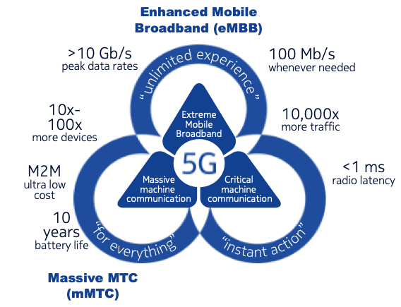
These three use cases require potentially contradictory network capabilities. As such, 5G networks need to be carefully architected to provide an optimal balance between service capabilities and network investment.
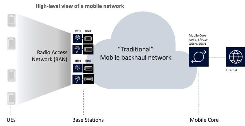
Figure 2: Typical mobile network architecture.
A traditional (pre-5G) mobile transport network has a number of distinct components:- User Equipment (UE): the end-user terminals that interface to the mobile network over the ‘air interface’. These include mobile handsets, data modems and tablets.
- Base Stations: provide the ‘air interface’ over which the UE connects to the mobile network. Base stations are located at cell sites and include elements of radio frequency processing (Remote Radio Head, RRH) and baseband processing (BaseBand Unit, BBU). For 4G networks, the base stations are referred to as eNodeBs. For 5G, they are called gNodeBs.
- RAN: describes the elements of the radio network used to provide radio connectivity to UEs. This includes components such as base stations and antennas.
- Mobile Core: a set of functions that includes signalling, authentication, subscriber management, mobility, and interfaces to external network and other control-plane and management-plane services. The mobile core tends to be centralized in 3G and 4G deployments.
- Backhaul network: the transport network that is used to carry traffic between the RAN and the mobile Core Network. For 4G networks this network is typically an IP transport network running over MPLS.
New elements of 5G technology
Before considering the impact of 5G technology on IP networks, you must appreciate the key architectural changes over previous generations. These changes can be broadly characterized as either changes in the Radio Access Network (RAN) or the mobile core network, which for 5G is termed the 5G core (5GC).
Radio Access Network (RAN) changes
New spectrum
5G opens up a lot more spectrum bands than have traditionally been used for mobile communications. Most mobile access networks in existence today have been deployed in the sub-3GHz radio spectrum.
The 5G spectrum is being allocated in three primary bands, as illustrated in Figure 3.

The two interesting spectrum bands that are being unlocked for 5G are the cmWave and mmWave ranges. These bands are characterized by higher frequencies and lower wavelengths. These higher frequency bands are attractive as they make available a lot more spectrum than is currently available within the sub-3GHz bands.
They do, however, come with a trade-off: the higher the frequency in use, the shorter the range we can achieve. This is due to the greater attenuation experienced by the higher-frequency RF transmissions.
A consequence of this is that mobile operators will need to densify their networks to provide complete coverage. Due to this, mobile operators are considering the use of low-band spectrum to provide coverage and high-band spectrum to provide capacity.
MIMO
Multiple-Input, Multiple-Output (MIMO) is a technique where multiple transmitters and receivers can be used at mobile cell sites and on UE to provide improved performance and capacity.
Implementations using up to 4 transmitters and receivers have been commonly deployed in 4G networks. 5G takes this a step further by introducing a much larger number of antennas — more than 16 — to provide the ability to send multiple independent data streams over the same, shared frequency- and time-domain resources within a single mobile cell (spatial multiplexing). The net effect is the multiplication of capacity within each cell site.
RAN evolution
There are many ways of implementing the 5G RAN, as a result of an effort to disaggregate the components of the base station.
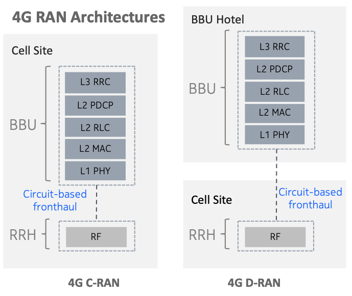
As seen in Figure 4, 4G networks use an element called the BaseBand Unit (BBU), which performs all of the different baseband processing functions. In addition, there is an element called the Remote Radio Head (RRH), which performs the Radio Frequency (RF) functions.
There are two potential architectures for deploying the RRH and BBU functions.
The first model, which is by far the more popular, is termed Distributed RAN (D-RAN) and deploys both the BBU and RRH functions at each cell site.
In the second model, the BBU function is placed at a more central location, typically called a BBU Hotel. This mode is termed as Centralized RAN and has been deployed by some operators as it allows them to simplify the equipment at the cell site resulting in reduced space and power requirements. In addition, it allows the BBU elements to be shared among multiple cell sites.
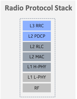
For the purpose of understanding 5G RAN deployment models, it is important to express the functions of baseband processing and RF processing in the form of the 3GPP Radio Protocol Stack, as illustrated in Figure 5.
In the same vein as other efforts in the industry, 5G attempts to disaggregate many RAN functions that have previously been vertically integrated. Figure 6 shows how we derive three new groupings of RAN functions based on splitting the functions of baseband processing.
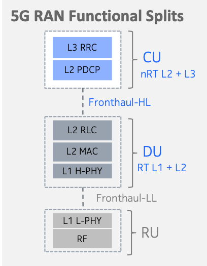
As we see above, the RAN functional elements can be split up into three functional units:
- Central Unit (CU): hosts the non-realtime functions of the L3 RRC and L2 PDCP layers.
- Distributed Unit (DU): hosts the realtime functions of the L2 RLC, L2 MAC and higher-layer PHY function.
- Radio Unit (RU): hosts the higher-layer PHY functions as well as RF processing.
The interface between the RU and the DU is called the Fronthaul-Low Layer (Fronthaul-LL) interface. As this interface requires low-latency transport (150-200 secs), the physical distance between the RU and the DU is constrained by that.
The interface between the DU and the CU is called the Fronthaul-High Layer (Fronthaul-HL) interface. This interface is also sometimes referred to as the Midhaul interface. Unlike the Fronthaul-LL interface, this interface is not as latency-sensitive so that the CU can be centralized further.
The three functional blocks of the CU, DU and RU can be physically decoupled and located at various tiers of the transport network resulting in different potential architectures (Figure 7).

The transport network for 5G takes on a different architecture compared to the traditional mobile transport network described earlier.

The choice of RAN architecture impacts the transport network in different ways. It requires low-latency transport between certain elements and different amounts of bandwidth depending on the communicating elements.
Mobile Core Network (CN) changes
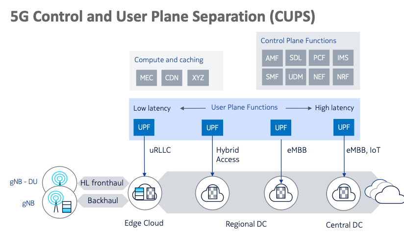
Control and User Plane Separation (CUPS)
The 5G core uses a Service-Based Architecture, which defines the 5G core components as Network Functions (NF) together with an API that can be used to invoke services. In addition, the 5G core decouples the user-plane (or data plane) from the control plane.
A key benefit of this capability is that the control plane can be centralized while the User Plane Function (UPF) can be distributed to various parts of the network to achieve low latency or to offload traffic closer to the actual users.
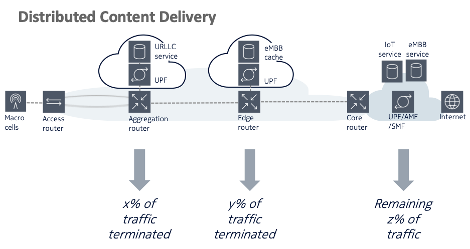
A key application of the CUPS capability is to allow mobile IP traffic to be broken out at different parts of the network. In Figure 10 , we see an example where:
- Ultra-Reliable Low Latency Communication (URLLC) traffic is terminated within the aggregation network resulting in lower end-to-end latency.
- eMBB traffic is terminated on eMBB caches at the network edge so that this traffic does not need to be carried further into the core.
- Non-critical IoT traffic is terminated at a core location.
Impacts on IP and optical transport networks
At a high level, the changes to 5G architecture and capabilities impose the following requirements on IP and optical transport networks:
- Higher capacity all the way from the access interfaces towards RAN elements to the mobile core to allow for the higher capacity of 5G traffic. Mobile operators are deploying 5g gNodeBs with 10GE or 25GE interfaces.
- Low-latency transport in the Fronthaul part of the network as well as for critical IoT applications.
- A move away from point-to-point connectivity to a multipoint forwarding architecture.
- Support of connectivity across traditional WAN and virtualized network functions to cater to the on-demand nature of traffic patterns and the necessity to dynamically create and scale network functions.
- Higher availability to meet the stringent demands of critical IoT applications.
- Packet-based synchronization techniques to allow effective disaggregation of RAN functions as well as the support of advanced RAN co-operation techniques.
Summary
As we have seen, the 5G network will be disaggregated in both the RAN and core domains.
The RAN domain can be split up into the RU, CU and DU functions. Different requirements will be imposed on the transport network connecting these functions, depending on where an operator chooses to physically locate them.
A similar approach is also being adopted for the mobile core with a clean separation of control-plane and data-plane functions. These functions will also need to be interconnected by a versatile IP network.
Due to the number and types of use cases supported by 5G, traffic patterns in a 5G network will be a lot more dynamic. The underlying transport network will need to allow programmatic control to allow it to react in near-realtime to the changing traffic demands of the mobile network.
For more information on some of these concepts, please refer to:
- https://www.3gpp.org/technologies/presentations-white-papers
- https://www.etsi.org/deliver/etsi_ts/123500_123599/123501/15.02.00_60/ts_123501v150200p.pdf
- https://www.nokia.com/blog/evolution-towards-cloud-ran-and-ecpri/
- https://www.slideshare.net/apnic/5g-technology-tutorial
I ‘m interested to hear your feedback on this post and thoughts on transport for 5G. Please write to me using the form below.
Paresh Khatri is the CTO for the IP and Optical Networks Business Group for Nokia Corporation in APAC.
The views expressed by the authors of this blog are their own and do not necessarily reflect the views of APNIC. Please note a Code of Conduct applies to this blog.
Very interesting description of the 5G deployment scenarios.
Is this a typo? Radio Unit (RU): hosts the higher-layer PHY functions as well as RF processing.
shouldn’t it say – hosts the lowerr-layer PHY functions?