

Perhaps every network engineer has got some understanding about OSPF LSDB (Open Shortest Path First Link State Database) but how many can read the topology table on a router and decide which LSAs are necessary and which are not for an ISP network? Objective of this blog is to provide some idea of how to keep OSPF topology table short and sweet, and optimize ISPs IGP (Interior Gateway Protocol) performance.
Out of five OSPF packet type, LSA (Link State Advertisement) messages are mostly carried into DBD(t2) and LSU(t4) packet data field. Depending on the purpose, network topology related information are mostly exchanged by around 1 to 11 LSA messages of OSPF routing protocol. We don’t need to go through all LSA type description now but as a design thumb rule it is good if the network routers generate less number of LSA. So less frequent SPF calculation for routers and quicker convergence time for the network. etc.
Design rule 1: For an ISP network our aim should be to try to keep entire OSPF operate by only Type1 & Type 3 LSA. Limit the flooding scope of LSA Type 1 by creating a hierarchical area around the backbone area (Area 0). Let the ABR (Area Border Router) send Inter-area link information by LSA Type 3. In a very limited case we may have LSA Type 2 generated. But LSA Type 4, 5, 7 and so on are not required if we can stop those LSAs requirement at the design and architecture level of IGP. Let see how we did that in our prototype training ISP network below.
I will try to explain this design principle based on following APNIC Training ISP lab topology diagram.

Here we built an ISP network where there are four region connected to the transport core at the middle. Individual regions are OSPF regular area i.e. Region 1 with a circle on the diagram is OSPF Area 1, same as Region 2 is OSPF Area 2 (R4, R6 & R5), Region 3 is OSPF Area 3 (R7, R9 & R8), Region 4 is OSPF Area 4 (R10, R12 & R11) and transport core is the OSPF backbone area 0. Router R1, R3, R4, R6, R7, R9, R10, R12 are internal routers for their area and Router R2, R5, R8 and R11 being the ABR.
If we look at the topology database for region 1 from R1 here:
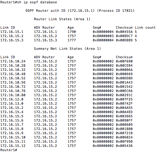
In Region 1 topology database we have Link LSA (LSA Type 1) generated by the Internal routers, which carry the actual link information for the area and Network Summary Link LSA (LSA Type 3) generated by the ABR (Area Border Router) R2. Purpose of this summary LSA by ABR R2 is to limit the flooding scope of Area 2,3,4 Link LSA to within the Area and generate a Summary link information and send it to other area i.e. Area 1 in this case. This makes a big difference when SPF (Shortest Path First) algorithm works on the topology database and need to converge quickly. Following is a screen capture (Partial) of R1 LSA Type 1 detail.
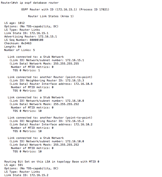
Following is a screen capture (Partial) of R1 LSA Type 3 detail.
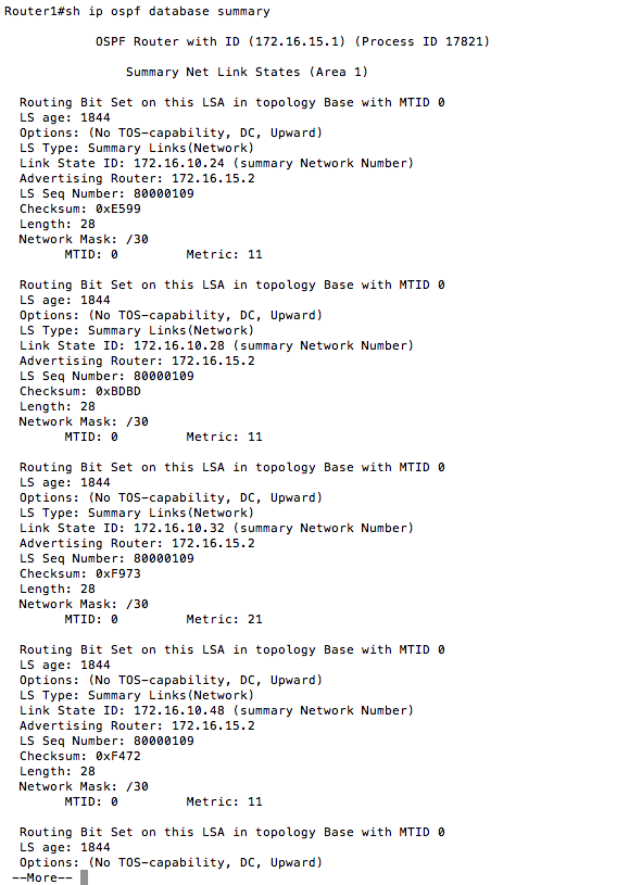
On the Figure 1 you probably have noticed that the link between routers are Ethernet type but here is no Network LSA (LSA Type 2) generated because we used following IOS command:
Router1(config-if)#ip ospf network point-to-point
Router1(config-if)#
Design rule 2: If the link is Ethernet/Gigabit Ethernet point-to-point which is most likely now a days, please use above command in Cisco IOS. It will help reduce LSA Type 2.
DR (Designated Router) on all broadcast multi-access links normally generate Type 2 LSA. It convert Type 1 LSA information received from DR other routers to a single Type 2 LSA and sent it to everyone within the broadcast multi-access network.
In our area 1 topology database Router2 being the ABR is sending a single Network Summary LSA (LSA Type 3) to R1 & R3 which is representing all link information received form other four area i.e Area 0, 2, 3 and 4 from the ABR of the corresponding area. For understanding purpose consider it as Incoming link update to area 1 generated as Type 1 LSA by internal routers of other Area (i.e. R4, R6, R7, R9 etc), then a single Summary LSA Type 3 to DR of Area 0. Then Type 2 LSA by the DR of backbone area to ABR R2 of area 1 and R2 will send a single Type 3 LSA to R1 & R3. Area 1 LSDB looks very simple by just one Summary LSA contains all other are routes. Also flooding scope of the LSA Type 3 is within the Area only.
Design Rule 3: There are two other Summary LSA (LSA Type 4 & Type 5) that an ABR/ASBR (Autonomous System Border Router) may generate some time. For example in Figure: 1 topology diagram a customer facing POP router R1 is connected to a customer router r13-CAR1 via interface fa0/0. This interface is normally OSPF passive, so IP prefixes configured on this interface will not be included into OSPF LSDB. If we need reachability to this link from the ISP network backbone then there are few options as follows:
Option1: Re-distribute static connected route into OSPF from R1
Option 2: Originate and aggregate prefix from R1 in BGP.
Option 1 is not very scalable and good choice for and ISP because this will generate Type 5 LSA by R1 and Type 4 LSA by R2 and the flooding scope will be to the entire OSPF network. This will also make a big difference if the ISP has thousands of customers connected. The growth of the ISPs IGP prefix will be directly related to the ISPs customer growth. Ten thousand customer will mean there will be at least ten thousand IGP route to ISP routers. Imagine how many Type 4 and Type 5 LSA entry will be there in the LSDB? What about if any customer link is flapping? IGP convergence will be a big issue. Troubleshooting will be a nightmare. So there is a big NO for option 1. For enterprise network it may be acceptable depending on the the size of the network.
Option 2 is very scalable for ISPs. On R1 a BGP network statement is originating an aggregated prefix (i.e /24 etc based on IP address plan). So none of the customer side point-to-point prefixes are included into OSPF LSDB but still have prefix repeatability via BGP. The growth of the ISPs IGP routing table is de-coupled from the customer growth. There is no LSA Type 4 and 5 generated by any routers. All external prefixes for ISP will be exchanged via BGP only and IGP will make sure BGP next-hop is reachable.
Design Rule 4: It is advisable for ISPs to keep OSPF area as regular area. Configuring any Stub/NSSA (Not-So-Stuby Area) may generate unwanted Type 7 LSA. ISPs also don’t prefer to use virtual Link.
Design Rule 5: ISPs IGP should carry only Infrastructure router Loopback and infrastructure point-to-point prefix. All external and customer point-to-point related prefixes should be announced by BGP.
This is how we can keep our OSPF LSDB short and sweet. Hope this discussion will help understand some basic principle of managing LSA entry in OSPF. Please feel free to send your question and comments below.
The views expressed by the authors of this blog are their own and do not necessarily reflect the views of APNIC. Please note a Code of Conduct applies to this blog.
Interesting blog Roman Bhai. Why ISP should not use stub area and what could be the LSA impact for stub?
Thanks Maruf.
If you create a stub are in OSPF it will generate another summary LSA of the default route. So one more LSA in addition. Also IGP function in ISP is to ensure BGP next-hop is reachable. Default route should handle by BGP. Hope this will answer your question.
Excellent write up. Agree 100% on each point, and have had very good success following the same philosophy. What you’ve outlined here, I would describe as an industry best practice, and common at any competent ISP.
I am curious, however… Why do you call out ISP’s specifically? While this is the approach I’ve followed for 10+ years at ISP’s, I have a hard time imagining an argument to do any different in an enterprise network or anything else? About the only thing I can imagine is running BGP on certain multi layer switches is probably a bad idea, but in that case, I’d say… “Use a switch like a switch, and a router like a router”, and just layer 2 pass through on your switch back to a capable router.
Thoughts?
Thanks for your comments.
Small enterprise usually don’t prefer to deploy BGP, though it could be good option for them.
sir I found this article is very useful specially people like me working as network design professional.
Will you please consider to write an article to talk about mpls design scenario where pe-ce routing is ospf.
by the way I have attended your workshop in medan and know you .
Thanks. Sure I will prepare one.
Good article. You made the complex thing very simple. Thanks. I have also enjoyed your MMNOG training yesterday.
One question on this document, for IP packet core network and MPLS traffic Engineering purpose we maybe need LSA Type 10 & Type 11. Then what to do?
Lin
Thanks Lin for your question. For MPLS TE if you do multi area TE using OSPF, it will generate those new LSA type to carry the RSVP TE related information to other area. So yes you will have these new LSA in your LSDB.
Well the information helps to resolve the internet issue and to optimize it to work safely and without any hurdle or error.