

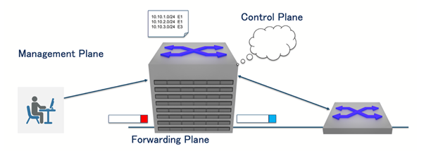
A router’s role is divided into three functional planes. The management plane handles local administration and monitoring tasks, such as maintaining counters and system state. The control plane communicates with neighbouring devices and computes routing information for the network. The forwarding plane deals with live traffic: When a packet arrives, its header is rewritten as needed, and the packet is forwarded to the next hop based on the Forwarding Information Base (FIB). This article focuses on the architecture of the forwarding plane.
RIB, FIB, and forwarding architectures
Routers maintain two primary databases: The Routing Information Base (RIB), built using routing protocols like OSPF, IS-IS, and BGP, and the Forwarding Information Base (FIB), which is derived from the RIB and used for packet forwarding.
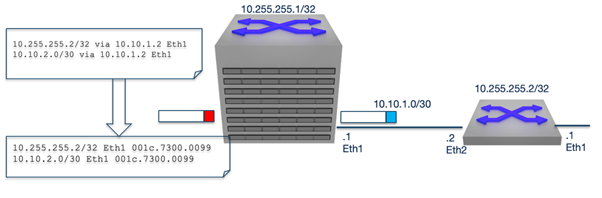
Forwarding architectures can be either centralized or distributed. In a centralized design, a single FIB resides on the supervisor alongside the control plane, while in a distributed design, the FIB is replicated to line cards, allowing each line card to forward packets locally.
Distributed forwarding in practice
In a distributed forwarding architecture, packet forwarding is carried out by switching chips on the line cards. Some implementations add an internal header to Ethernet frames, while others convert frames into fixed-size cells for internal transport.
The Broadcom DNX/Jericho series exemplifies a cell-based distributed forwarding architecture. Packet processing in DNX occurs in stages: Incoming packets are first examined by the ingress packet processor, which determines the output destination using the FIB. The ingress transmit processor then segments packets into cells and sends them to the fabric interface. At the egress side, the receive processor reassembles the cells into full packets, and the egress transmit processor applies any necessary header updates, such as next-hop DMAC changes, VLAN tagging, or tunnel encapsulation, based on instructions from the ingress stage.
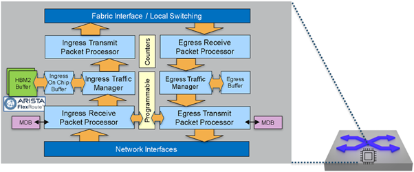
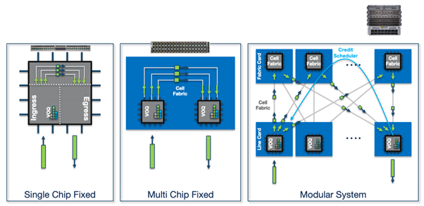
The DNX architecture also includes the Rammon fabric chip, which forwards cells between forwarding chips. Vendors may deploy both modular and fixed system designs using Jericho and Rammon chips.
Despite differences in port count or system size, the forwarding architecture remains consistent: The ingress pipeline determines the egress point and segments the frame for the fabric, while the egress pipeline reassembles the cells and transmits the packet.
Traffic scheduling on line cards
When a packet arrives at the ingress line card, it requests credit to forward the packet to the egress line card. If the egress line card is busy, the packet is held in the ingress buffer until credit is granted. This traffic scheduling mechanism ensures orderly packet flow across the line cards.
Distributed control plane architectures
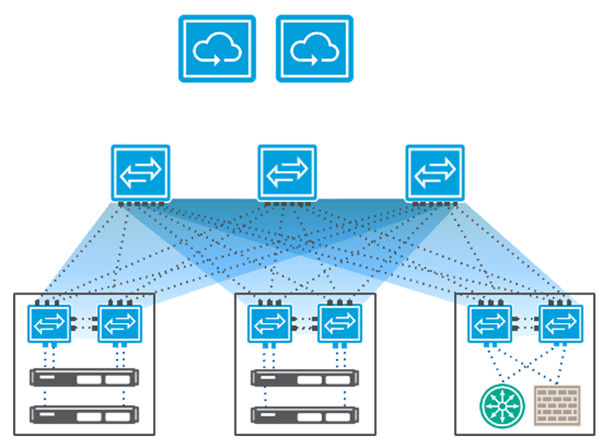
Distributed data plane concepts are not limited to traditional routers. OpenFlow, for instance, separates the control plane and data plane, with controllers running on x86 servers to handle centralized decision-making, while spine switches form the fabric and leaf switches act as line cards.
The InfiniBand Subnet Manager operates similarly, discovering the physical topology, calculating optimal paths using its own routing algorithm, and automatically programming new paths in the event of failures.
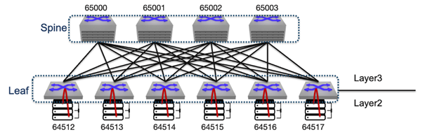
Modern Ethernet routing, often implemented as IP Clos architectures, also relies on distributed path calculations. Unlike InfiniBand, Ethernet distributes routing decisions across network nodes, eliminating single points of failure and improving network resiliency. If a port fails, the local switch can immediately determine an alternate path, preventing a single system failure from disrupting the entire network.
AI data centre fabrics
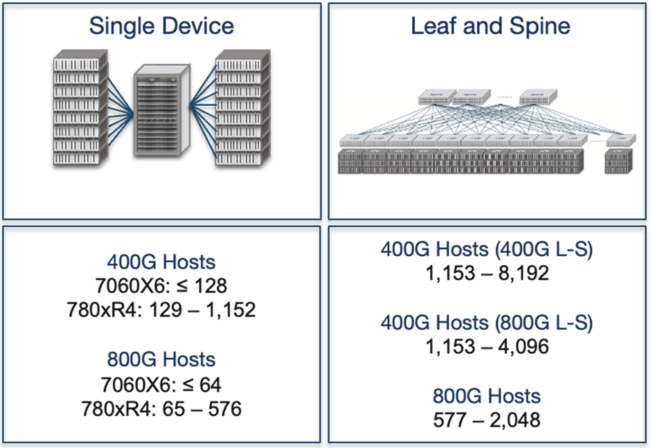
AI data centres, which are among the largest networks in operation today, require lossless Ethernet to efficiently distribute workloads across XPUs (accelerators such as GPUs, TPUs, and other specialized processing units). To support large-scale host deployments, network architects use either single-chassis systems or leaf–spine architectures. Single-chassis systems simplify traffic control but are limited in scale, whereas leaf–spine architectures scale to thousands of hosts but require advanced traffic management mechanisms such as Data Centre Quantized Congestion Notification (DCQCN), Explicit Congestion Notification (ECN), and Priority Flow Control (PFC).
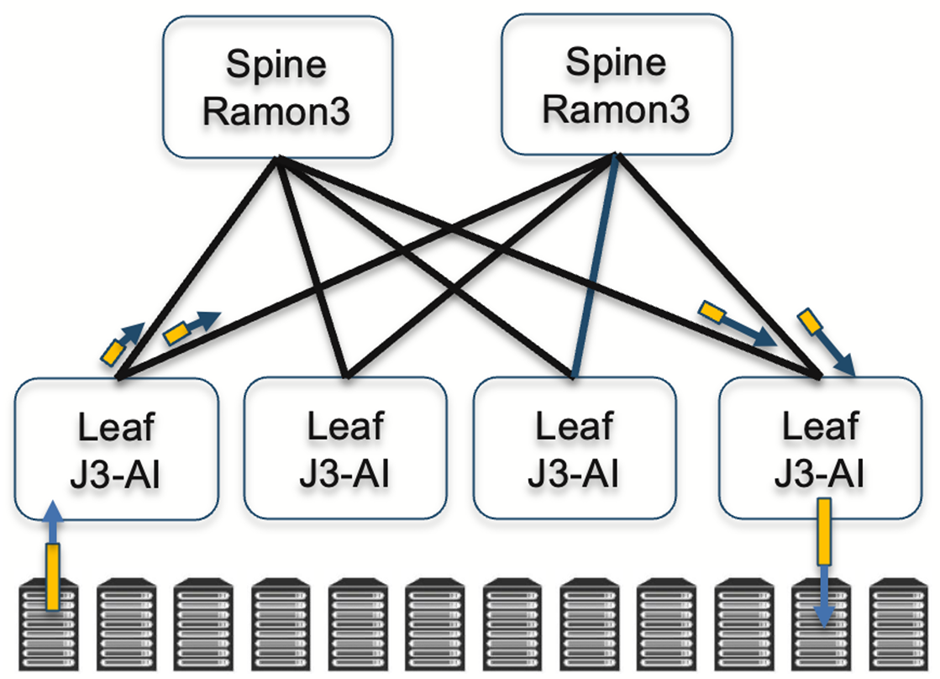
Broadcom’s Jericho3 AI Ethernet Fabric extends modular principles network-wide. In this design, Ramon chips handle fabric cards in spine switches, while conventional Jericho switching chips operate on leaf switches. This architecture allows AI datacentres to scale without compromising performance or resiliency.
Disaggregated designs, such as the Telecom Infra Project’s Disaggregated Distributed Backbone Router (DDBR), combine a centralized control plane with a distributed data plane. Arista’s Distributed Etherlink Switch similarly runs leaf and spine switches independently, with schedulers coordinating across the network. From the perspective of GPUs or accelerators, these disaggregated systems behave as a single unified network. So it would be a distributed control plane and a distributed data plane.
Ultra Ethernet, a next-generation AI Ethernet fabric designed to support up to one million XPUs or accelerators, takes this concept further by implementing both host-based and hop-by-hop scheduling mechanisms. It also incorporates advanced congestion and flow control techniques, including Network Signal Congestion Control (NSCC), Receiver Credit Congestion Control (RCCC), Link-Level Retry (LLR), and Credit-Based Flow Control (CBFC), enabling reliable, high-performance operation at extreme scale. The traffic scheduling is not only network-wide but also end-to-end.
Conclusion
Distributed forwarding and modern data plane architectures are essential for building scalable, resilient networks. From traditional routers to AI datacenter fabrics like Jericho3 and Ultra Ethernet, separating the control plane from the data plane and distributing forwarding ensures high performance, fault tolerance, and the ability to handle massive workloads. Understanding these designs is critical for next-generation Ethernet and AI network deployments.
Watch Shishio’s presentation on this topic at APNIC 60.
Shishio Tsuchiya is an SE Lead at Arista Networks. He has been a network engineer since 1997.
The views expressed by the authors of this blog are their own and do not necessarily reflect the views of APNIC. Please note a Code of Conduct applies to this blog.