

In the past 15 years, there has been a spate of growth in global submarine cable builds, expanding capacity to regions that already had them, but also connecting many new places that only had satellite for connectivity, until now.
More interestingly, most submarine cable builds have been undertaken by content providers (Google, Microsoft, Meta, and so forth), and less so by traditional telecommunications companies. The reason for this is that more than 65% of all Internet traffic can be accounted for by these content providers. This is important to appreciate because the amount of data centre to data centre traffic these providers need to haul around the world is so significant, it makes more sense for them to build their own submarine cable systems in lieu of purchasing capacity from existing network operators in their busiest markets.
As the amount of bandwidth required to grow the Internet has increased, so too have the technologies pivotal in getting us there. From basic modulation to Dense Wavelength Division Multiplexing (DWDM) and now to Spatial Division Multiplexing (SDM), we have reached a point where submarine cables are now carrying 1.5Pbps of annual traffic, as of 2023.
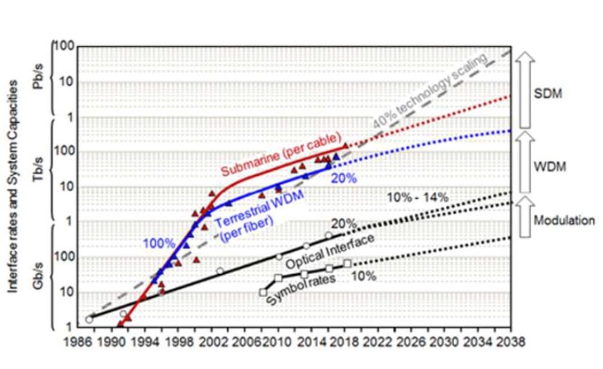
These advancements have been supported by significant progress in optical technology in a short space of time. Direct Detection was the primary method of data transmission in DWDM networks up until 2010. But with this technology, only 10Gbps of capacity could be carried by a single wavelength.
In 2010, Coherent Detection came along, and with that, we were now able to carry 100Gbps of capacity per wavelength, over much greater distances than before. Coherent Detection sparked a development race that saw wavelength capacity grow by 8X within the span of a little over a decade (2010 – 2022), where we are now able to support 800Gbps of capacity per wavelength.
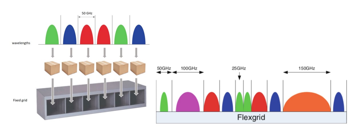
One of the key components of DWDM technology that helped get us to these unprecedented levels of capacity handling was the shift from fixed-grid to flexible grid (flex-grid) DWDM systems. In fixed-grid systems, wavelengths had to fill a fixed 50GHz channel. Whether that channel was filled or not with capacity did not matter, the system still consumed 50GHz of bandwidth. With flex-grid systems, channel bandwidth can be broken down more granularly to as low as 12.5GHz (and in some cases, even 6GHz). With this, you can assign wavelengths to channels in a tighter spacing to make more efficient use of the overall spectrum, which results in more capacity being carried for different types or levels of services on the system, without the penalty of spectral inefficiency.
Prior to 2010, all submarine fibre cables were dispersion-managed systems. Chromatic dispersion is a phenomenon that occurs in a fibre cable due to different frequencies travelling at different speeds through it. It can also include a delta in different frequencies of the same wavelength travelling at different speeds. This leads to signal distortion. To resolve this issue, the industry deployed dispersion-managed fibre cables, which allowed Direct Detection to offer 2.5Gbps – 10Gbps wavelengths on such cables. The dispersion was compensated for by alternating lengths of positive and negative dispersion fibres within the fibre span itself.
From 2010 onward, Coherent Detection was invented, and this gave cable system operators the ability to compensate for chromatic dispersion digitally in the Digital Signal Processor (DSP), allowing the cable system to increase overall capacity by at least 50%. For example, Apollo went from 650Gbps ultimate to 11Tbps ultimate, just due to Coherent Detection technology.
In fact, current fibre cables are high (positive)-dispersion cables, because Coherent Detection does not perform well on fibres with low chromatic dispersion. The low chromatic dispersion when combined with Coherent Detection increases the likelihood that symbols on different wavelengths will propagate together, which will change the refractive index of the fibre at the same time through the Kerr effect (the change in the refractive index of a material in response to an applied electric field), leading to non-linear effects such as cross-phase modulation (XPM).
From 2014 to 2019, all new submarine fibre cables were built on uncompensated, positive- and high-dispersion fibre cables. High-order modulation schemes such as 8QAM (Quadrature Amplitude Modulation) and 16QAM for high spectral efficiency (previous fibres used Quadrature Phase Shift Key (QPSK)) were used to increase capacity.
These uncompensated fibre cables were of extremely high quality, ultra-low attenuation (less than 0.15dB/km), large effective areas to reduce non-linear penalties (150 square microns), short amplifier spacing (about 56km), high amplifier pump power, and a wider amplifier bandwidth (4.8THz). All this made it possible to deliver up to 28Tbps of capacity on a single fibre across 6,500km. For an eight fibre-pair system, this could deliver 224Tbps for the entire cable system.
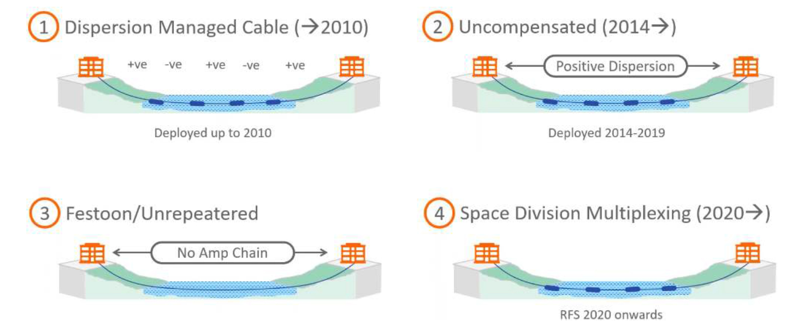
From 2020, new cable systems have now been designed based on SDM. SDM, in and of itself, is not a technology as much as it is a philosophy. Because of the extreme success of Coherent Detection on uncompensated fibre cables, we are approaching the physical limits of how much capacity we can transmit in a single fibre pair, which is called the ‘Shannon Limit’ (Figure 3). So rather than continue to find ways to improve SNR (Signal-to-Noise Ratio) to gain more capacity per fibre pair, it is easier to simply add more fibre pairs to increase overall cable system capacity.

The optimization of repeater power and spacing is the latest approach to how we can maximize subsea cable capacity:
- Longer amplifier spacing means that we can use a lower launch power.
- Lower amplifier power means that we can have a lower Optical SNR (OSNR), which equates to a lower effect from non-linear penalties.
- Pump sharing means that we can conserve electrical power in the cable system, allowing us headroom for future use.
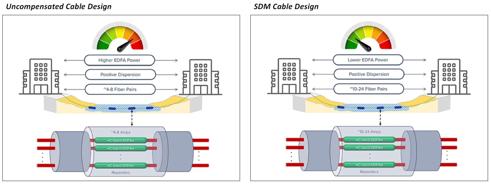
The net result is lower fibre pair capacity, but more fibre pairs, which delivers a higher total cable system capacity. As mentioned, this is a philosophy, not a technology. Moreover, because optical power levels in SDM cables are much lower and within the linear regime of the fibre, very large-effective-area fibres are not necessary. This allows for the use of cost-optimized fibres, with a typical effective area of around 80 square microns.
This is unlike prior uncompensated fibre cables which, while they also had positive dispersion, required high electrical amplification because they typically held no more than eight fibre pairs within the cable system. Uncompensated cables maximized spectral efficiency and spectral capacity per fibre pair, which resulted in high amplification power to achieve up to 800Gbps per fibre pair.
SDM cables on the other hand, due to having up to 24 fibre pairs in the system (and more planned for the future), sacrifice spectral efficiency and capacity per fibre pair, which lowers amplification power. In other words, the lower optical efficiencies are compensated for by having additional fibre pairs, which is how SDM cables push the boundaries of cable system capacity. Moreover, because of the low electrical demands from the system, there is plenty of headroom for future scenarios.
Having said all that, SDM cables do come with their own administration challenges due to the extensive matrix of landing points, hand-offs, participants, and transponders. Some of the questions that can arise from being part of an SDM system are:
- When is the cable Ready For Service (RFS) date?
- How do you dynamically manage the spectrum?
- Who operates the cable system?
- How do you perform testing quickly?
- How do you provision quickly?
- Who do you call when things go wrong?
- Does the cable owner restrict which DWDM vendors are allowed onto the system?
The technical challenges to managing and operating SDM cables are being resolved through tools that help automate testing, provisioning, spectrum management and troubleshooting. How this will be standardized between the Submarine Line Terminating Equipment (SLTE) and the wet plant vendors remains to be seen. Suffice it to say, some degree of manual work can be expected, as far as is practical.
SDM is developing at a fast pace. Current work is focused on increasing the number of fibre pairs to at least 32, with a target of 40 already under consideration as well. The main limitation of the number of fibre pairs in the system will be the number of amplifiers that can be deployed and their spacing.
The other limitation to increasing the number of fibre pairs in a cable system is the diameter of the submarine cable itself. Typically, submarine cables are 17mm in diameter, although 20mm cables are also available for use. The 17mm cables are often a preferred option because of lower material cost and loaded cable weight in the cable-laying ship. Standard high-performance submarine cables have an outer diameter of 250 microns, which can allow for up to 16 fibre pairs within a 17mm cable, or 20 fibre pairs within a 20mm cable. Trying to pack more fibre pairs into these cables would lead to micro-bending losses in the fibres, which would lower optical performance by a great deal.
One option to solve this is to move to smaller-diameter fibre. This would mean adopting 200-micron-wide fibres that are in use on terrestrial networks, for deployment in submarine applications, without significant loss in optical performance. A 20% reduction in fibre diameter would yield a 50% increase in the number of fibres that can fit into the cable without incurring micro-bending losses. This means that we can fit 24 fibre pairs inside a 17mm submarine cable. The next generation of SDM cables is very likely to adopt this option.
Furthermore, fibre manufacturers are looking at ways to lower fibre thickness by decreasing the fibre cladding diameter from 125 microns to 100 microns. They are also looking at lowering the coating diameter to between 130 and 140 microns. This could open the door for 48 fibre pair cable systems, depending on how well we can optimize power utilization for the cable.
Of course, as time goes by, there will be a limit to how many fibre pairs we can support in an SDM cable as well, considering that cable repair times increase dramatically with SDM cables. When we get to this point, it may be necessary to rekindle the C-Band and L-Band (C + L) transmission options, and/or novel fibre types like Multi Core Fibre (MCF) and Hollow Core Fibre (HCF). But these novel fibres need to gain favour in terrestrial networks first (where there is currently no use-case) before they can bleed over into the submarine world, because vendors and operators do not want to use submarine-specific MCF compensation Application Specific Integrated Circuits (ASICs), due to the fact that terrestrial and submarine transponder technologies have converged.
The good news, however, is that in all this development, current transponder technology can operate successfully over these new cable systems without special developments required.
Here are some examples of planned and in-force SDM-based submarine cable systems:
| SDM Cable System | Fibre Pairs | RFS |
| Dunant | 12 | 2021 |
| H2HE | 16 | 2021 |
| Amitie | 16 | 2021 |
| Equiano | 12 | 2022 |
| APRICOT | 16 | 2024 |
| JUNO | 20 | 2024 |
| 2Africa | 16 | 2024 |
| Bifrost | 12 | 2024 |
| MEDUSA | 24 | 2024 |
| Hawaiki Nui | 12 | 2025 |
| Caribbean Express | 18 | 2025 |
| SMW-6 | 10 | 2025 |
| CSN-1 | ? | 2025 |
Even though SDM cables are currently state-of-the-art in the submarine world, it does not mean uncompensated cables will no longer be deployed. Not all routes require a lot of fibre pairs, especially short ones, or spans where not a lot of funding is available. In such cases, uncompensated cable systems will remain viable, especially if they are unrepeated.
Another area of improvement is the electrical conductor used to power the submarine cable system. Usually, submarine cables use copper as the conductor. However, aluminium is under consideration because it offers a lower voltage drop per unit of distance compared to copper and is also cheaper as a raw material. But before aluminium can find a home in submarine cables, significant testing will be required to ensure it can meet the standard 25+-year lifespan of the cable.
Mark presented this material during the APOPS 1 session at APRICOT 2023. Watch the presentation now:
Mark Tinka is the Head of Engineering at SEACOM with 24 years experience as a network engineer building ISP networks and Internet Exchange Points across Africa and the Asia Pacific. He is now based in Johannesburg, South Africa.
The views expressed by the authors of this blog are their own and do not necessarily reflect the views of APNIC. Please note a Code of Conduct applies to this blog.
Lovely