

I had the opportunity to participate in the New Zealand Network Operators Group meeting (NZNOG 2024) in Nelson earlier this month. This article was prompted by a presentation from Thomas Weible of Flexoptix at NZNOG on the topic of coherent optical transceivers.
The first generation of optical transmission systems used simple on/off keying (OOK) of the digital signal into light on the wire. A source of light was focused onto the end of the fibre cable, and a light sensor was placed at the other end. The overlay of digital signals onto such systems was rudimentary in the first instance — the detection of light was a ‘1’ and the absence of light was a ‘0’. Very early optical systems used light-emitting diodes at one end and photodiodes at the other.
However, we wanted more from these optical systems. We wanted higher speed and longer reach. Both objectives can be addressed, at least initially, by changing the source of light to a laser, giving both longer reach by increasing the ability to inject larger amounts of optical power into the cable and permitting faster-switching properties. To achieve further improvements in both speed and distance for optical systems it’s necessary to include consideration of the cable itself.
Fibre optic cable issues
Fibre optic cables represent a set of optimizations within a larger collection of constraints.
In 1970, a team at Corning made a fibre that had a loss rate of 17db/km with a light source of 630nm wavelength. This introduction of low-loss fibre was a critical milestone in fibre optic cable development. Working to further reduce this loss rate, it was noted that longer wavelengths had lower rates.
This led to work in increasing the wavelength of the light source, using near-infrared light, and changing the silica doping agent in the fibre from titanium oxide to germanium oxide. With these two changes, using an 850nm light source, the achievable fibre loss rate dropped to less than 5db/km, which is a truly awesome change in the loss profile! This 12db drop is a 16-fold improvement in the ‘transparency’ of the fibre. This result is close to the theoretical minimum attenuation at 850nm. The effort then concentrated on using light sources with longer wavelengths.
By 1976, researchers had developed laser light sources that operated at 1200nm, which could drive fibre with attention of less than 0.46db/km, and by the end of the 1970s they were using 1550nm lasers and achieving less than 0.2db/km.
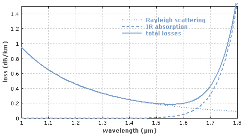
The fundamental loss limits for a silica-based glass fibre are Rayleigh scattering at short wavelengths and material absorption in the infrared part of the spectrum. A theoretical attenuation minimum for silica fibres can be predicted at a wavelength of 1,550nm where the two curves cross (Figure 1). This has been one reason for today’s use of laser sources and receivers that work in this portion of the spectrum.
However, there is an interplay between the cable and the light signal which is exacerbated when the cable span is increased. There are three main forms of signal distortion in fibre systems (Figure 2).
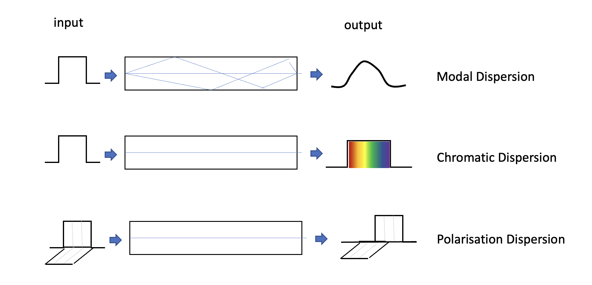
- Modal dispersion is seen in multi-mode fibre. There are several paths through a large core fibre. Some paths use internal reflection off the edges of the core, while other paths are more direct without any internal reflection. The reflected paths are longer so a single square wave input pulse will be dispersed into a waveform that has a strong resemblance to a Gaussian distribution output signal. Single-mode fibre that uses an 8-9µm core diameter does not have this form of signal impairment, because if the core diameter is sufficiently small, preferably at no more than 10x the signal wavelength, the internal reflection paths are minimal compared to the path length directly along the core.
- Chromatic dispersion is due to the property that lower frequencies travel faster in fibre cable, and if a signal uses a broad spectrum of frequencies (necessary to obtain higher cable bandwidth), then the signal will become dispersed on the transit through the fibre and the lower frequency component will arrive earlier than the higher frequency component. To reduce the level of signal degradation and increase the signal bandwidth G.655 fibre (the most common fibre used) was engineered to have zero chromatic dispersion at 1,310nm as this was the most common laser source at the time. Signal dispersion can be compensated by placing dispersion-compensating fibre lengths in every repeater, assuming that you wanted to compensate for chromatic dispersion (which in Dense Wave Division Multiplexing (DWDM) cable systems is not necessarily the case).
- Polarization mode dispersion. Silica fibre has small-scale radial variations, which means that different polarization components will propagate through the fibre at various speeds. This can be corrected by placing a Polarization Mode Dispersion (PMD) compensator just in front of the receiver. This is performed after the wavelength splitting so one unit is required for every wavelength. This requirement of PMD compensation per wavelength was an inhibitory factor in the adoption of 40Gbps per wavelength in long cable systems in DWDM systems.
In addition, there are non-linear effects. A linear effect is where the effect is proportional to power and distance, whereas non-linear effects are threshold-based and only appear when a particular threshold is crossed. For linear effects, a common response to compensate is to increase the input power, but for non-linear effects, this will not necessarily provide appropriate compensation to mitigate the signal distortion.
In a light pulse, the leading part of the pulse changes in power very quickly and this rapid change causes a change in the refractive index of the medium if the optical power level is high enough. The result is there is self-phase modulation where the pulse interferes with itself. In a Wave Division Multiplexed (WDM) system there is also cross-talk modulation, where the signals (pulses) in one wavelength interfere with the signals in other wavelengths, There is also four-wave mixing where two wavelengths of sufficiently high power levels create two phantom side signals spaced equally apart, which will interfere with adjacent signals in a DWDM configuration.
The conventional approach to these non-linear effects was to limit the optical launch power (which limits the reach, or inter-amplifier distance in a cable run), and also to use cable with high levels of chromatic dispersion (so that the pulse energy is dispersed by chromatic dispersion effects) and to use a large effective core area in the fibre, both of which were properties of G.652 fibre.
In the search for longer reach and higher capacity of optical systems, we have devised a new set of non-linear mitigations, which include Nyquist subcarriers, Soft Decision Forward Error Correcting (SD-FEC) codes, Super-Gaussian Probabilistic Constellation Shaping (PCS) and non-linear compensation. All these techniques rely on improvements in the Digital Signal Processing (DSP) in the transceivers.
In the 1980s the G.652 fibre systems were suited to the 1,310nm lasers that were used at the time. In the search for lower attenuation, we shifted to 1,550nm lasers, which were placed at the minimum attenuation point for the media, but the large core area (80µm2) meant high chromatic dispersion which had to be compensated for with lengths of Dispersion Compensating Fibre (DCF), which effectively cancelled out the advantages of 1,550nm lasers.
There was a brief time when we used G.653 Dispersion-Shifted Fibre (DSF), which used a narrower core to shift the zero chromatic dispersion point up to 1,550nm. However, in the mid-1990s we started to use DWDM systems, and here the aim was to have some chromatic dispersion to reduce the crosstalk factors in the fibre.
These days we tend to use G.655 Non-Zero Dispersion-Shifted Fibre (NZDSF) that provides some level of chromatic dispersion at 1,550nm to reduce the crosstalk effects in DWDM systems centred around 1,550nm, with a core area of 55µm2.
The next step is G.655 Large Effect Area Fibre (LEAF) with a larger core area of 72µm2. This is a variant of G.655 with a low band dispersion area and a large effective area. This is a better configuration for single wavelength 10Gb transmission.
Coherent technology
At this point, we can come back to the original question of how to extract greater capacity and reach from optical systems.
The first major innovation was to use Wavelength Division Multiplexing (WDM). This had been used from the very early days of radio where the use of frequency-tuned transmitters and receivers allowed for completely independent signals to share a common radio path. In fibre systems, the use of WDM allows a single fibre cable to be simultaneously used by several independent data streams, each encoded into its own bearer frequency band. Initially, each signal used OOK encoding within its allocated wavelength band. The narrower wavelength band used by WDM systems means that chromatic dispersion is less of a factor within each wavelength.
The next major innovation is the shift from OOK encoding to coherent encoding systems. This was introduced into the mainstream of fibre optic transmission systems in 2010. Various forms of radio and voice digital models had adopted more complex forms of signal processing to improve signal capacity, including phase and amplitude modulation of the common bearer signal for many years, and this approach was then ported across to the signal processors for fibre systems.
The use of phase and amplitude modulation for high-speed optical systems relies on advanced digital signal processors that exploit greater gate counts and higher processing capabilities. Such signal processing does not alter the signal-to-noise profile of the transmission system but attempts to optimize the spectral efficiency of the signal.
Why is this useful?
Using these digital signal processors it’s possible to modulate the signal in each lambda by performing phase modulation of the signal. (Figure 3)
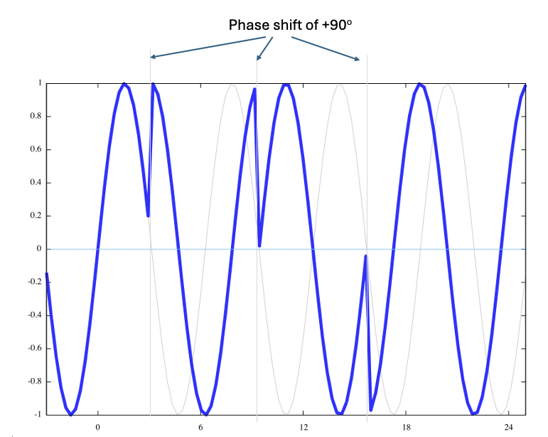
Phase shift keying does not alter the basic baud rate of the system. The additional signal is encoded into the relative phase difference between an unshifted reference oscillator and the received signal.
Quadrature Phase Shift Keying (QPSK) defines four signal points, each separated at 90-degree phase shifts, allowing two bits to be encoded in a single symbol (Figure 4).
A combination of two-point polarization mode encoding and QPSK allows for three bits per symbol. The practical outcome is that a C-band-based 5Thz optical carriage system using QPSK and DWDM can be configured to carry a total capacity across all its channels of some 25Tbps, assuming a reasonably good Signal-to-Noise ratio (SNR). The other beneficial outcome is that these extremely high speeds can be achieved with far more modest components. A 100G channel is constructed as 8 x 12.5G individual bearers.
This encoding can be further augmented with amplitude modulation. Beyond QPSK there is 8QAM that adds another four points to the QPSK encoding, adding additional phase offsets of 45 degrees at half the amplitude. 8QAM permits a group coding of three bits per symbol but requires an improvement in the SNR of 4db.
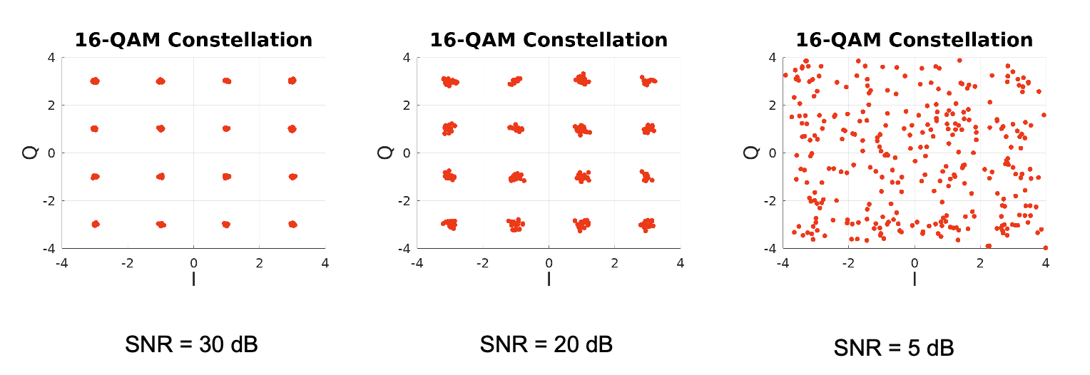
16QAM defines, as its name suggests 16 discrete points in the phase-amplitude space, which allows the encoding of four bits per symbol, with a further requirement of 3db in the minimum acceptable SNR. The practical limit of increasing the number of encoding points in phase-amplitude space is the SNR of the system, as the higher the number of discrete points in the phase-amplitude space of the encoded signal, the greater the demands placed on the digital signal processor (Figure 5).
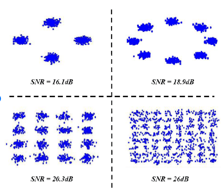
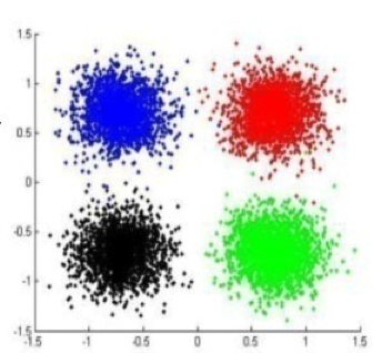
Another way to look at this relationship between SNR and the maximal number of discrete points in phase-amplitude space is to regard the impact of noise as shifting the certainty of the resolution of a symbol in phase-amplitude space. Higher levels of noise cause received symbols to ‘blur’ in phase-amplitude space, as shown in Figure 6.
Even when the SNR indicates that a particular encoding is theoretically feasible, the level of signal processing required to distinguish between the various encoding points increases in line with the processing capability of the signal processor.
Additional transceiver capabilities
These days, optical modules can perform more functions than modulation and demodulation of the optical signal.
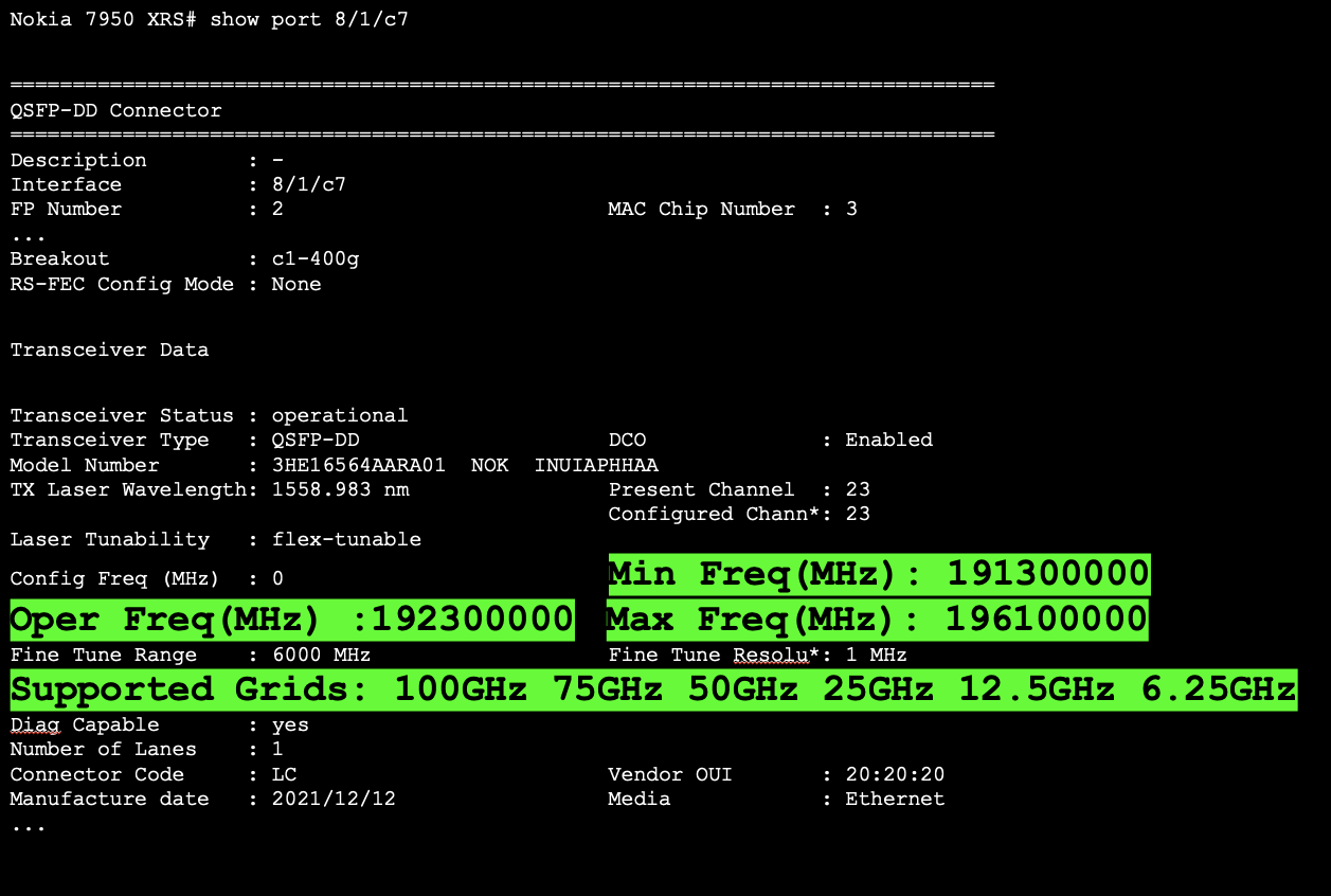
We are seeing tuneable lasers in these modules, allowing the network operator to configure the module to a particular frequency, rather than having the frequency pre-set at the factory (a screenshot of a Command-Line Interface (CLI) -based tuneable laser is shown in Figure 7).
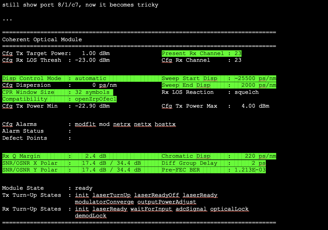
It is also possible in some modules to perform a correction for a cable system’s chromatic dispersion properties (Figure 8). Rather than using a customized length of correcting fibre the digital signal processor can be used to perform the necessary compensation.
Another consideration is the physical size of these units. While the first of these coherent light transmission systems used an entire interface card to drive a single cable, the industry has pressed successfully for ever higher cable densities, requiring ever-smaller module form factors. This means that the DSP needs to be physically smaller which in turn implies a requirement for higher-density silicon chips and higher efficiency heat dissipation in the smaller form factor.
Table 1 relates the evolution of these coherent systems over the past 14 years, relating the base baud rate, signal capacity per wavelength and per cable and the technology used by the digital signal processor.
| Year | Mode | Baud | Capacity/Lambda | Cable Capacity | DSP |
| 2010 | PM-QPSK | 32 GBd | 100G | 8T, C-Band | 40nm |
| 2015 | PM-16QAM | 32 GBd | 200G | 19.2T, Ext C | 28nm |
| 2017 | PM-32QAM | 56 GBd | 400G | 19.2T, Ext C | 28nm |
| 2019 | PM-64QAM | 68 GBd | 600G | 38T, Ext C | 16nm |
| 2020 | PS-PM-64QAM | 100 GBd | 800G | 42T, Ext C | 7nm |
| 2022 | PCS-144QAM | 190 GBd | 2.2T | 105T, Ext C | 5nm |
It is unclear where it all goes from here. There is no clear future for chip technology for the DSP beyond 3 to 5nm, so further improvements in capacity in such systems may well lie in areas of further refinement of the laser and the associated fibre properties.
Future
We are by no means near the end of the path in the evolution of fibre optic cable systems, and ideas on how to improve the cost and performance still abound. Optical transmission capability has increased by a factor of around 100 every decade for the past three decades. While it would be foolhardy to predict that this pace of capability refinement will come to an abrupt halt, it also must be admitted that sustaining this growth will take a considerable degree of technological innovation in the coming years.
There is still much we can do in this space!
The views expressed by the authors of this blog are their own and do not necessarily reflect the views of APNIC. Please note a Code of Conduct applies to this blog.