

This post is the second in our SRv6 series. Read ‘Introduction to SRv6 network programming’.
As of 2019, Segment Routing over IPv6 data plane (SRv6) has been deployed in eight large-scale networks; supported by more than 25 hardware implementations at line rate; implemented in 11 open-source platforms/applications; and, importantly, is undergoing IETF standardization (RFC 8402, RFC 8754).
In this post, we will go through the numerous use cases that have been deployed as of February 2019.
VPN over Best-Effort 5G Slice use-case
In the SRv6 solution, any use-case can be expressed as a stateless Network Program only requiring IPv6 and Segment Routing Headers (SRHs). No other encapsulation or protocol is required.
For this use-case, the network program contains only one instruction and as a result, the instruction is encoded in the destination address (DA) of the outer IPv6 header with no need for an SRH. Only Ingress and Egress Provider Edge (PE) routers need to be SRv6 capable whereas the other core nodes are just performing plain IPv6 forwarding.
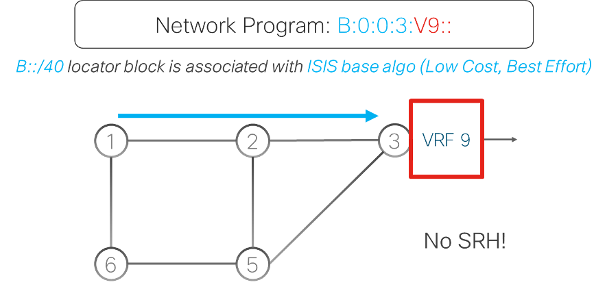
In this example, the SRv6 nodes are assigned SRv6 locators from an address block (B::/40). Assume that Egress PE gets assigned locator B:0:0:3::/64. This Egress PE advertises its locator B:0:0:3::/64 in IS-IS, and advertises the customer’s Virtual Private Network Segment ID, or VPN SID, (B:0:0:3:V9::) in Border Gateway Protocol (BGP). This VPN SID comprises a Locator part (B:0:0:3) and a Function part (V9).
The Ingress PE, encapsulates customer packets in the outer IPv6 header with DA equal to that customer’s VPN SID B:0:0:3:V9::. The nodes bring the packet to Egress PE via the IS-IS shortest path to the Locator prefix B:0:0:3::/64 using plain IPv6 forwarding. At the Egress PE, the function part (V9) is mapped to a VPN instruction, which decapsulates the SRv6 encapsulation and does a look-up in the customer Virtual Route Forward (VRF).
This very simple network program implements a VPN service over a Best-Effort 5G Slice, without using an SRH. There are several examples of service deployed in live networks.
While the transport service is based on IPv6/SRv6, the transported payload can be of any type: IPv4, IPv6 or L2.
VPN with Low-Delay 5G Slice – Flexible-Algorithm option use-case
The Flexible Algorithm (Flex-Algo) enables the building of customized routing algorithms in IS-IS.
In this use-case, all nodes run two IS-IS algorithms: Best-Effort and Low-Delay Algorithms. The Best-Effort Algorithm is the default algorithm (algo0) that computes the shortest path using the Interior Gateway Protocol (IGP) metric. The Low-Delay Algorithm (Flex-Algo128) computes the shortest path using the measured link delay as a metric.
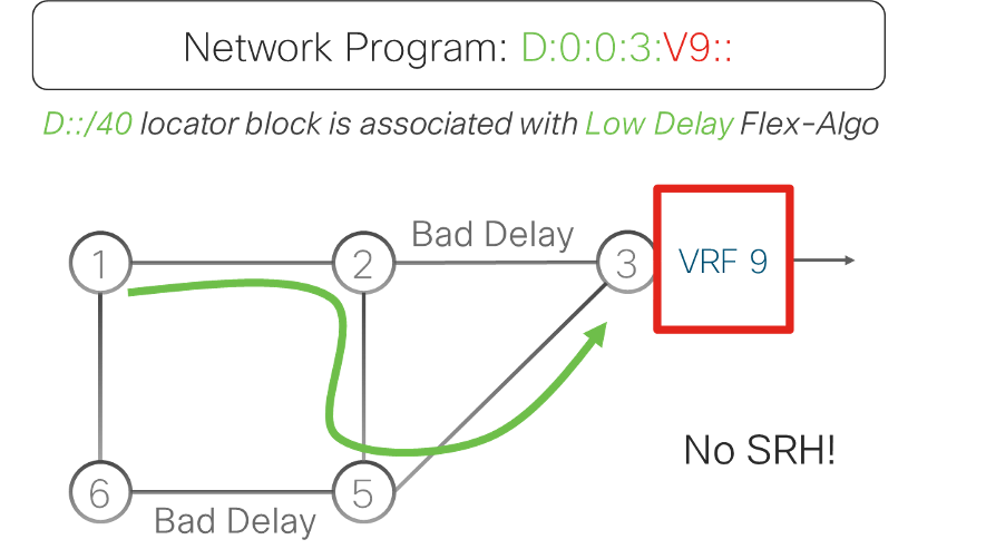
SRv6 locators for Flex-Algo128 are allocated from a new and distinct address block (D::/40). Assume Egress PE gets allocated Flex-Algo128 locator D:0:0:3::/64, which is being advertised in IS-IS (under the Flex-Algo128). Low-delay VPN SID (D:0:0:3:V9::) is advertised using BGP.
At Ingress PE, customers packets with low-delay SLA are encapsulated in an outer IPv6 header with a DA equal to the customer’s low-delay VPN SID (D:0:0:3:V9::). Packets are routed to the Egress PE using the low-delay path computed by Flex-Algo128. Egress PE decapsulates the SRv6 encapsulation, does a lookup for the inner packet header in the customer VRF (V9) and forwards the packet accordingly.
This simple network program implements a VPN service over a Low-Delay 5G Slice, without using an SRH. Again, there are several examples of service deployed in live networks.
SNORT firewall, VPN and Low-Delay Slice use-case
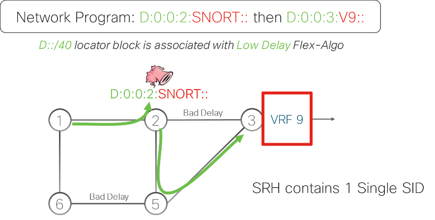
This use-case is adding a SNORT firewall service on top of the VPN and Low-Delay Slice service. The network program to deploy this use-case requires two instructions: “go to node 2 via Low-Delay Slice and apply SNORT” and “go to Egress PE via Low-Delay Slice and forward in VRF 9”.
The first instruction is encoded as D:0:0:2:SNORT::, where “D:0:0:2” is the low-delay locator of node 2 and “SNORT” identifies the SNORT function on this node. The second instruction is encoded as D:0:0:3:V9::, where “D:0:0:3” is the low-delay locator of node 3 and “V9” is the VPN function, as explained in the previous section.
The Ingress PE maps the received customer packet to the policy and encapsulates this packet in an outer IPv6 header with two instructions. The first instruction (D:0:0:2:SNORT::) is encoded in the DA of the outer header. The second instruction (D:0:0:3:V9::) is encoded in the SRH that has been added in the outer packet header.
The packet is forwarded to the low-delay locator of node 2 (D:0:0:2) via the Low-Delay Slice. SNORT processes the customer packet to enforce the security rules and then updates the DA of the packet with the second instruction. Next, the packet is forwarded to the Egress PE using the locator of the second instruction (D:0:0:3). The Egress PE decapsulates the SRv6 encapsulation and lookup in the inner packet in the customer VRF.
This use-case exemplifies the power of the SRv6 solution to integrate any kind of service by just adding new instructions to the SRv6 network program at the Ingress PE.
Topology Independent Loop-free Alternate Fast Re-route (TI-LFA)
TI-LFA provides fast-reroute protection of the traffic for link, node, or Shared Risk Link Group failures.
The IGP pre-computes a backup path for each destination and pre-installs these backup paths in the data plane, ready to be activated. Upon a local failure, the node activates the TI-LFA backup paths at once within 50 ms, restoring connectivity for the impacted traffic streams. Once the IGP has converged and has updated the forwarding entries, the backup paths are deactivated and new backup paths are computed and installed.
TI-LFA leverages the SR steering functionality to guarantee 100% protection coverage in any topology.
TI-LFA is simple to operate as the IGP automatically computes the per-destination backup paths using performant algorithms. The TI-LFA backup path is the post-convergence path, the path that the traffic will follow when the IGP has converged after the failure. This is the most optimal backup path and it avoids intermediate flaps via an alternate path.
TI-LFA is a local functionality with each node providing protection for its local resources. To benefit from TI-LFA, a full network upgrade is not required as it can be deployed incrementally – each addition of a TILFA-enabled node increases the level of protection.
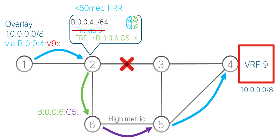
In the example below (Figure 4), VPN service traffic flows between nodes 1 and 4. Node 1 encapsulates the service traffic in an IPv6 header with IPv6 destination address B:0:0:4:C2::, that is the End.DT4 SID that node 4 advertises for this VPN service. If you are not familiar with the term ‘End.DT4’, see my previous post in this series .
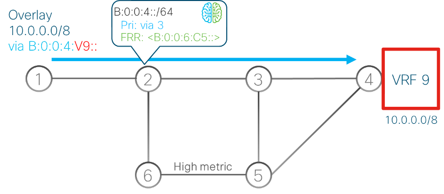
TI-LFA is enabled on node 2 and the IGP pre-computes the TI-LFA backup paths for all destinations. For the VPN service traffic, it computes a backup path for destination prefix B:0:0:4::/64. The TI-LFA backup path for this destination, in case of link 2, 3 failure, is via nodes 6 and 5.
To steer the traffic on this backup path, node 2 uses the End.X SID B:0:0:6:C5:: advertised by node 6. This SID steers the packets to node 6 and via the high-metric link to node 5.
If the link between nodes 2 and 3 fails, node 2 activates the pre-computed TI-LFA backup path within 50 ms of failure detection. With the traffic flowing over the backup path, the service connectivity is restored. After the IGP converges to the new topology, the backup path is deactivated and new backup paths are computed and installed.
Again, there are several examples of this service deployed in live networks.
Load-balancing
The SRv6 solution provides day-1 optimum load-balancing contrary to Multiprotocol Label Switching (MPLS), which is still having issues with load balancing. In MPLS, the entropy for Equal-Cost Multi-Path (ECMP) selection is in the inner IP packet, so the routers must dig down through the MPLS label stack to get access to the IP header used for hashing.
In SRv6, the Ingress PE computes a hash on the customer packet and writes the result in the Flow Label field of the added outer IPv6 header. The rest of the network leverages this Flow Label to do ECMP selection by just looking at the outer header with no need to dig down through the layers of encapsulation.
Seamless incremental deployment
The SRv6 solution offers a seamless incremental deployment model.
If we look at the SRv6 VPN service, it only requires PE upgrades as the core of the network is doing simple plain IPv6. If we want to deploy Traffic Engineering (TE) services, we only need some TE way-points at some specific locations in the network.
The same applies for Fast Reroute, since TI-LFA is a local, per-router functionality that can be deployed incrementally.
Thanks to this seamless incremental deployment model, eight large-scale deployments have been completed in just two years at Softbank, Iliad, China Telecom, LINE corporation, China Unicom, CERNET2, China Bank and Uganda MTN.
Prefix summarization
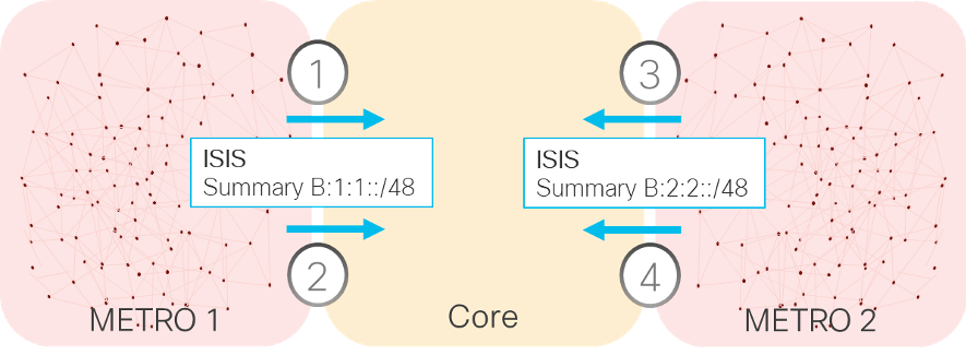
In MPLS networks, the lack of prefix summarization led to very complex inter-AS options A/B/C and hierarchical BGP labels. Thanks to SRv6 prefix summarization, which is an inherent benefit to IP networks, SRv6 gets rid of all of these complexities.
For example, if we have two metro networks, each having hundreds of thousands of /64 locators (SRv6 capable routers), a single summary can be advertised into the core by each metro. So, the core will only be carrying the locators of the core nodes and the summaries of the metro networks. This an extremely powerful feature.
SRv6 native scale
SRv6 is highly scalable. Many use-cases do not even use an SRH; VPN services (L3VPN, Pseudo-Wire, eVPN), Egress Peer Engineering (EPE), Low-Latency, Disjoint-Slicing, or Optimal Load-Balancing just require a single instruction that is encoded in the IPv6 DA field.
If an SRH is needed, only one or two instructions are required in most cases.
In addition, SRv6 prefix summarization provides a major scaling gain as it extends the network slices across domains, enabling the same scalability approach to multi-domains at ultra-scale with hundreds of thousands of nodes.
SRv6 provides a much simpler solution as it eliminates the following unnecessary protocols: RSVP-TE, LDP, MPLS data plane, UDP-VXLAN and NSH. The fewer the components, the better the reliability.
SRv6 automation
As the SRv6 solution is simple by design, the automation of SRv6 turns out to be simple as well.
The SRv6 solution provides an automation package for the well-known, multi-vendor automation tool Network Services Orchestrator (NSO). The package takes care of many configuration and automation tasks:
- Address allocation for the loopbacks and the physical interfaces.
- Segment Identifier (SID) allocation for low-cost and low-delay 5G slices both in multi-domain and intra-domain.
- Address summarization and redistribution between domains.
- Configuration of latency measurements with the ability to enable Topology-Independent Loop-Free Alternate (TILFA) and Bidirectional Forwarding Detection (BFD) for liveness of the links as well as BGP VPN-based services.
SRV6 SID allocation
Operators can choose between using private IPv6 addresses available to anyone or their public IPv6 addresses assigned by their Regional Internet Registry.
The SRv6 deployments at both Iliad and SoftBank revealed that the allocated address space for SRv6 SIDs is negligible with respect to their available IPv6 address space.
Iliad deployed the SRv6 solution across their networks using a /40 sub-block of the private IPv6 ULA FC00::/8 address space. This is less than one-billionth of the private addressing space and hence is negligible.
SoftBank uses a /40 prefix out of the /20 public IPv6 prefix assigned to them by APNIC. This /40 prefix is used for all their SRv6 services. This is just one-millionth of their available public address space and hence is negligible.
In my final post, I will discuss SRv6 micro-instructions.
Clarence Filsfils is a Cisco Systems Fellow, with 25-years’ experience leading innovation, productization, marketing and deployment for Cisco Systems.
The views expressed by the authors of this blog are their own and do not necessarily reflect the views of APNIC. Please note a Code of Conduct applies to this blog.
Thank you 🙂
Simple and brief explanation. Very helpful to understand the power of SRv6. Thank you!
Fantastic and to be honest Clarence, please post more things like that related either to SR-MPLS or SRv6 and toward which solution the market is going on when we speak specifically about SRv6.
Very informative and I really enjoyed it. I hope to see more and especially for SRv6 policy.
Using FC00::/8 without IANA permission is the request for trouble. This prefix is not open for usage yet – a registry is needed.
FD00::/8 is available for this purpose.