
As AI workloads scale to thousands of accelerators, the interconnect fabric (also known as a scale-up fabric) for rack-scale systems is under intense scrutiny. Significant advancements are reshaping scale-up connectivity in 2025.
The UALink Consortium has released its 1.0 specification, a memory-semantic interconnect designed for efficient communication between accelerators. Broadcom released its own specification for scale-up fabric and aims to standardize it through OCP. The Ultra Ethernet Consortium has defined several enhancements to standard Ethernet that can help scale-up fabrics.
This article discusses the requirements of scale-up fabric, provides a technical overview of UALink’s four-layer protocol stack and switch fabric architecture, and Broadcom’s Scale-Up Ethernet (SUE). It then discusses their performance, latency, and readiness for AI-driven rack-scale systems.
Scale-up fabric
A scale-up fabric is a high-speed, low-latency interconnect system explicitly designed to connect accelerators, such as GPUs or AI processors, within a single server or rack-scale system. This enables efficient memory-semantic communication and coordinated computing across multiple accelerator units.
Scale-up fabric should have the following features to maximize bandwidth with minimal latency between accelerators.
High bandwidth/ single-stage fabric
The fabric must deliver extremely high bandwidth between the GPUs, significantly greater than what a typical scale-out interconnect can provide, to handle heavy communication demands between accelerators efficiently. These accelerators frequently exchange large tensor or pipeline parallelism data, which requires distributing data evenly across multiple links to avoid congestion and reduce communication latency.
To achieve this high bandwidth without increasing latency, the fabric is typically organized as a single-stage network, meaning data packets travel through exactly one switch from source to destination, without intermediate hops.
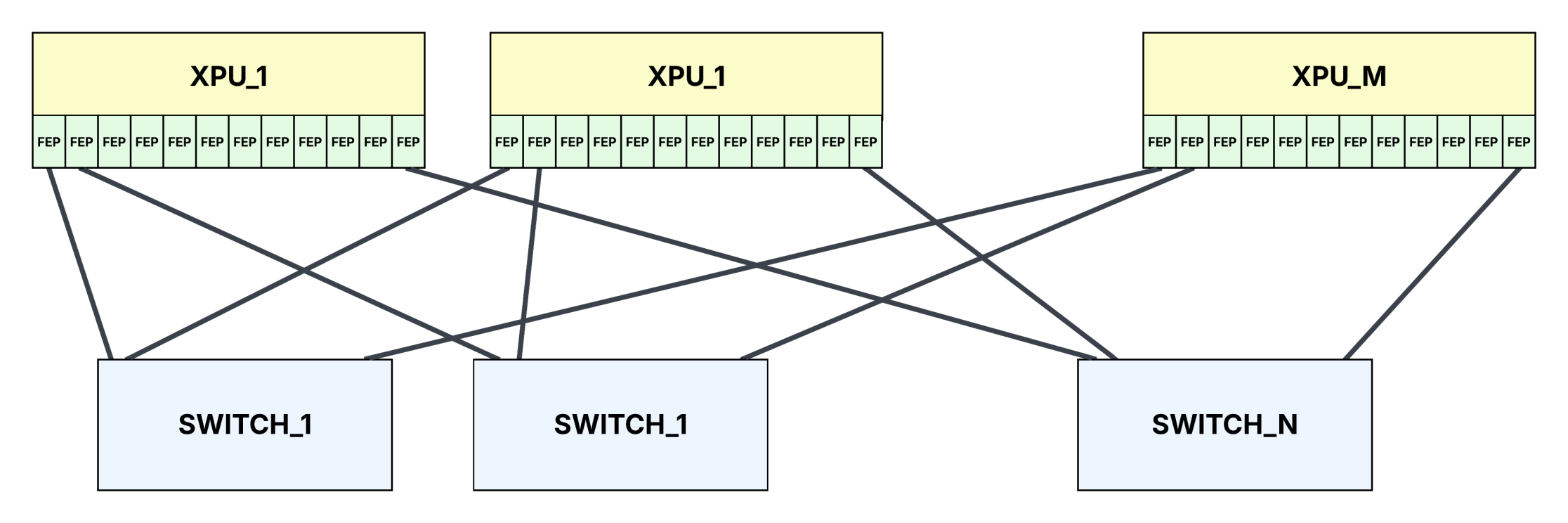
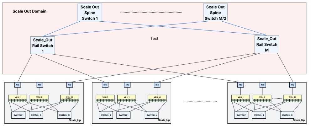
Scale-up fabric usually has multiple parallel fabric planes, each plane consisting of a dedicated scale-up switch. In an N-plane fabric design, there are N separate switches. Every accelerator has dedicated links to each of these N switches. Thus, when an accelerator needs to send a large transaction to another accelerator, it can simultaneously distribute traffic across all the fabric planes. This parallel approach significantly boosts network throughput and ensures accelerators communicate with low latency without bottlenecks.
With MxM scale-up switches, up to M accelerators can be interconnected within one pod or accelerator group, each having dedicated connections to all fabric planes.
Shared memory semantics
In the scale-up fabric, the XPUs should be able to do load and store operations on remote accelerator memories as if they were locally attached. In other words, the aggregate memory of all the accelerators should appear as a single pool for each accelerator.
Modern processors, GPUs, and accelerators typically operate on 256B cache line-sized data units. Hence, the scale-up fabric should support reading and writing 256B entries to remote accelerators with these load/store instructions.
While cache coherency is needed for HPC applications, it is not a hard requirement for AI workloads, which typically do not involve multiple accelerators modifying memory contents simultaneously.
Lossless
The fabric must be lossless and provide reliable links because the load/store memory semantics, unlike Remote Direct Memory Access (RDMA) transactions commonly used in scale-out scenarios, cannot tolerate packet loss. The endpoints can choose to implement go-back-N retransmission (retransmitting all packets following a lost packet) or selective retransmission (retransmitting only lost packets) at the transport layer.
While retransmissions ensure data integrity, they introduce memory overhead and latency. For instance, with a fabric round-trip time (RTT) of around two µs and a total bandwidth of 9.6Tbps, each accelerator needs about 2.4MB of retransmission buffering. This buffer isn’t huge but increases chip area and power consumption. Retransmissions also add latency, potentially disrupting tight synchronization and degrading performance in tensor or pipeline-parallel data exchanges.
On the other hand, skipping retransmission has downsides too. Any uncorrected link errors or memory Error Correction Code (ECC) errors would trigger memory access faults, halting GPU or accelerator contexts and possibly aborting kernels. Clearly, uncorrected errors are unacceptable in a scale-up fabric.
Thus, while transport-layer retransmissions can be a necessary fallback, the primary fabric design goal must be robust, lossless communication that avoids retransmission overhead altogether.
Hop-by-hop flow control at finer granularity
To prevent buffer overflows and head-of-line blocking, the fabric should support hop-by-hop flow control on a per-port and per-traffic-class (or virtual channel) basis. The per-traffic-class flow control enables requests and responses that use different traffic classes to pass through the switch fabric without blocking each other.
Having end-to-end credits between accelerator pairs for read/write requests and responses can also help prevent sustained in-cast scenarios where multiple accelerators send traffic to the same destination accelerator.
No software overhead for inter-accelerator communication
No additional software overhead should be present at the endpoints to send memory read/write operations to the remote memories. In other words, GPU-direct RDMAs that require software to do Queue Pair (QP) assignment, memory registration, virtual space allocation, and so on, are not ideal for scale-up transfers as latencies increase to the tens of microsecond range.
GPUs/accelerators usually send load/store operations across the scale-up fabric by packing and encapsulating these transactions with transport and data link layer headers in the hardware without any software intervention.
Most intra-server AI traffic, both for training and inference, involves large transfers ranging from a few kilobytes to hundreds of megabytes, far exceeding 256-byte load/store transactions. One can wonder whether load/store semantics offer significant advantages over lightweight RDMA that uses pre-established QPs and virtual address spaces to minimize software overhead. However, breaking large transfers into smaller transactions can achieve high link use and lower latencies, which enables accelerators to begin processing data immediately upon receiving smaller segments. For this reason, many hyperscalers continue to favour load/store semantics for intra-accelerator communications.
High bandwidth efficiency
Bandwidth efficiency is the number of bits in the data frame that carry the actual payload data. Bandwidth efficiency should be as close to 100% as possible. The fabric should carry memory read/write requests, responses, and credits between endpoints with minimal protocol overhead.
Ultra-low latency
The end-to-end latency should be as low as possible. This is important for applications that cannot overlap or mask the time spent on communication between the accelerators with useful computational work.
For inference workloads, the cumulative increase in latency (which is not hidden) between accelerators, especially with Mixture of Experts (MoE) models and chain-of-thought reasoning, can become noticeable to users. These models require multiple intra-server GPU communications for each token generation, and the final response may involve generating thousands of tokens.
Low jitter
Predictable latency with minimal jitter is essential for the efficient execution of AI workloads, especially large-scale inference and tightly synchronized training tasks. Compilers and runtimes often attempt to optimize performance by overlapping GPU-to-GPU communication operations with independent computation. To effectively schedule these overlaps, the system relies heavily on stable and predictable communication latencies.
Memory ordering guarantees
The fabric must preserve memory ordering guarantees. Specifically, the fabric must deliver any memory read or write targeting the same 256-byte-aligned address region of a remote accelerator in the order the source accelerator issued them. Reordering such transactions could violate memory consistency and lead to incorrect program behaviour.
Best Power Performance Area (PPA)
This is true for any switch. It is all the more critical for rack-scale systems to reduce the chassis power and cost (and the silicon cost as well as the cost for thermal management of the switch cards)
UALink for scale-up
Ultra Accelerator Link (UALink) is a high-speed, memory-semantic interconnect designed specifically for scale-up. Thus, the protocol attempts to address all the requirements listed in the previous section.
The fabric can scale-up to 1,024 accelerators and enables direct load/store access to the memories of remote accelerators as if they were locally attached.
A UALink Switch (ULS) is a specialized, high-performance switch that provides non-blocking connectivity between accelerator endpoints communicating using the UALink protocol. A Pod consists of all the accelerators connected via UALink Switches. UALink supports the concept of virtual pods inside each pod. Accelerators belonging to different virtual pods won’t be able to communicate with each other even if they belong to the same pod.
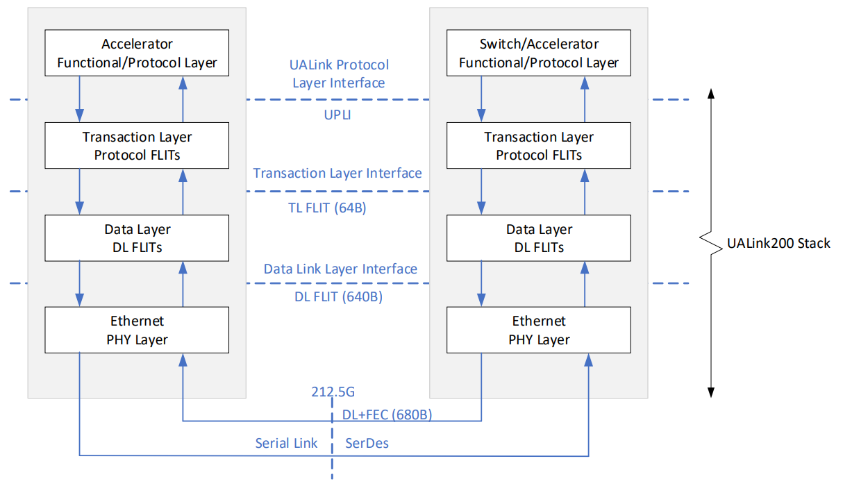
UALink is organized as a four-layer stack: A Protocol Layer called the UALink Protocol Level Interface (UPLI), a Transaction Layer (TL), a Data Link Layer (DL), and a Physical Layer (PL).
UALink Protocol Level Interface
UPLI is the logical protocol layer that generates and interprets the requests and responses exchanged between the accelerators. It supports memory semantic operations, like memory read/write or atomics. Every Request from an Originator is matched with a Response from the Completer, forming a complete transaction. Thus, these protocol layer transactions are two-sided.
UPLI has separate virtual channels for read and write requests and responses. These channels operate independently and have no ordering requirements between them.
This protocol allows up to 256B read/write with 64-byte beats. Aligning each transaction to write up to 256B (cache line size) ensures that data naturally aligns with the memory subsystem’s granularity, preventing partial cache line accesses and simplifying hardware design.
The protocol layer may support end-to-end credits per channel between any two accelerator pairs to manage buffer usage and prevent overflow.
Each accelerator has as many UPLI interfaces as the number of fabric planes it supports.
Transaction Layer
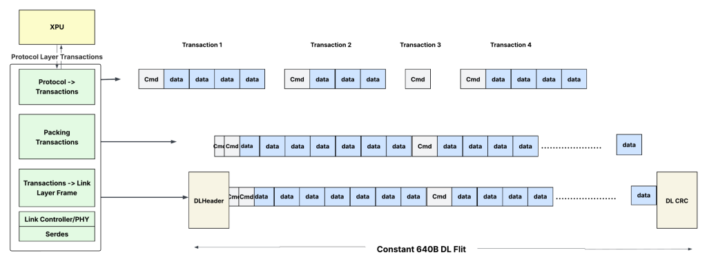
The Transaction Layer (TL) converts the UPLI messages into a sequence of 64B units called TL flits for transmission. Each flit is further subdivided into two half-flits, each carrying either control or payload data for transactions.
- The control half-flits may contain information such as source and destination accelerator IDs, virtual channel numbers, and memory addresses, while the data half-flits carry write or read data.
- TL flits can be packed back-to-back to achieve very high link use.
On the receiving side, the TL extracts the read responses from the incoming sequence of TL flits and sends them to the appropriate UPLI channels.
Data Link layer
The Data Link (DL) layer reliably conveys TL flits between two directly connected (point-to-point) UALink devices, such as an accelerator and a switch port.
It takes the 64-byte TL flits and encapsulates them into larger data frames, 640 bytes in size, with Cyclic Redundancy Check (CRC) and a header. At the physical layer, each 640-byte DL flit is mapped to a 680-byte RS FEC code word. This enables FEC and CRC to apply cleanly to each data link unit.
UALink supports a reliable link protocol with link-level retransmission (LLR). Any corrupted or lost DL can be retransmitted at the link level. Since the uncorrectable FEC error or a CRC error is localized to one DL flit, partial frame retransmissions are avoided.
The DL layer also supports credit-based flow control per port (and probably per virtual channel) to avoid blockage of the head-of-line.
Physical Layer
UALink 1.0 builds directly on IEEE Ethernet PHY technology, supporting 200Gb/s per lane via the 212.5Gb/s serial signalling defined by IEEE P802.3dj. Its PHY is essentially a standard Ethernet SerDes with minimal changes.
UALink supports port speeds of 200G, 400G, and 800G, using one, two, or four 200G lanes per port. Leveraging Ethernet PHY allows UALink to reuse established technologies, such as 64B/66B line encoding and KP4 Forward Error Correction (FEC), within the Physical Coding Sublayer (PCS).
While standard Ethernet often employs a 4-way interleaved FEC for better burst-error correction, which adds latency, UALink optionally supports simpler 1-way or 2-way FEC interleaving, trading off some error correction strength for reduced latency.
Thus, UALink allows vendors to reuse existing 100G/200G Ethernet SerDes IP and firmware with minimal modifications, significantly lowering the development risk and total cost of ownership (TCO). It also enables the systems to use existing copper cables, connectors, retimers, and future optical modules developed for Ethernet.
UALink switch
The UAL switch connects multiple accelerators in a rack-scale or server. To be on par with the next-generation Ethernet switch fabric radix, the first-generation chips may target 102.4T (512x200G) with a 512×512 internal switch fabric.
The switch fabric can switch at the TL flit boundaries per virtual channel. This constant-sized flit switching (unlike variable-sized packet switching in Ethernet switches) simplifies the design of cross-bars, schedulers, and datapath elements and lowers latencies throughout the switch’s core.
Standard Ethernet for scale-up
The UAL 1.0 spec has just been published. It will be at least 1.5 to 2 years before the first-gen UAL switches are available for rack-scale systems. In the meantime, can standard Ethernet fill the gap for scale-up networks and get ahead of UAL? Let’s see…
- Standard Ethernet does not support reliable links with link-level retries. While it supports FEC at the endpoints, it is not sufficient on its own for lane speeds of 100G and above. A typical post-FEC BER of 1e-15 means one error every 2.78 hours for a 100G link, which is not acceptable for intra-accelerator workloads.
- The flow control mechanism is based on PFC. While PFC is known for causing head-of-line blocking in Clos topologies, it works decently in single-switch systems. However, it requires twice the buffering compared to credit-based flow control mechanisms.
- The merchant silicon shallow buffer switches currently available (51.2Tbps) may not be highly optimized to achieve latencies below 500ns.
- These switches come with many features that are not needed for scale-up and are thus not optimized for area/power.
- Currently, no open standard defines the protocol layer or how transactions from that layer are encapsulated in standard Ethernet frames.
While standard Ethernet switches and custom protocols can still be used to build scale-up fabrics, they may not achieve the best performance or use.
Can next-gen Ethernet switches target scale-up?
Reliable and lossless links
The UEC draft specifies Link Layer Retry (LLR) and Credit-Based Flow Control (CBFC) per traffic class for standard Ethernet links. This can be achieved by injecting special control Ordered Sets into the 64b/66b data stream to carry acknowledgements (ACKs) and negative acknowledgements (NACKs), and credit updates simultaneously with data packets. If implemented, these features provide reliable lossless interconnects in Ethernet switches similar to their UALink counterparts.
Broadcom’s Scale-Up Ethernet (SUE) framework
Broadcom released the SUE framework at the OCP Global summit in April 2025 to address concerns about standard Ethernet for scale-up. The specification refers to the LLR and CFBC features. While the draft does not explicitly mention whether these features are from the UEC spec, Ethernet scale-up switch implementations can follow the UEC spec when implementing these features to enable multi-vendor interoperability.
- The protocol layer in the spec looks very similar to UPLI except that the transactions are one-sided. In other words, there is no explicit ACK for writes. They also have the concept of virtual channels to map different transaction types to different virtual channels to reduce HOL.
- Unlike UALink 1.0, the SUE framework gives accelerator architects the flexibility to pack their proprietary protocol-layer transactions inside Ethernet frames. This flexibility is crucial, as it allows the accelerators to reuse their existing protocol-layer transactions logic and simply encapsulate them with Ethernet frames for transport across the fabric.
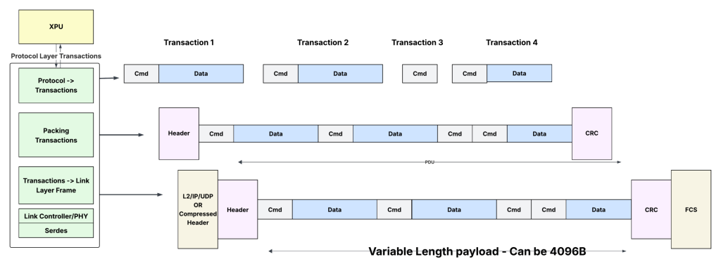
Transactions can be packed as commands followed by optional data. Commands can be read/write requests or read responses. The command typically consists of the destination memory address, channel number, length of the command/data, and other details. The data is the data associated with the commands (write/read response). Some commands (like the read request) do not have associated data.
- Each accelerator can have multiple SUE interfaces, matching the number of switch planes to which it is connected.
- The transactions to per-destination and per-traffic-class are queued in their respective queues at the accelerator’s Fabric end point (FEP) logic.
- If a queue has multiple transactions, they can be merged to create a Protocol Data Unit (PDU), which can be as large as 4KB. Standard Ethernet frames thus have the advantage — the Ethernet header overhead can be amortized across several transactions.
- The spec specifies adding a reliable header (for retransmission) and the CRC for this PDU and sending it out using an AI header (a newly defined header that merges and compresses the standard L2/L3 headers to reduce the header overhead) or the standard Ethernet/IP/UDP headers.
- The hardware can limit the number of transactions that can be merged, reducing variability in packet sizes.
- The logic for packing the transactions is relatively simple. It just concatenates full transactions headed to the same destination/channel to form larger PDUs.
- On the receive side, the SUE logic decapsulates the Ethernet header, extracts the sequence of commands and data, and sends them to the accelerator protocol interface.
End-to-end latencies/jitter
Historically, Ethernet networks have been perceived as lossy, with jitter and variable latencies. While it is true for standard Ethernet switches, new offerings from merchant silicon vendors claim low and predictable latencies through the switches.
An Ethernet switch designed explicitly for intra-data centre applications can drastically reduce latencies by eliminating unnecessary packet processing features, reducing pipeline depths, and scaling down data structures, buffers, and queues. It can also enable cut-through forwarding and other optimizations. With these optimizations, some merchant silicon vendors claim latencies of ~250-300 nanoseconds in advanced process nodes. However, the actual latencies depend heavily on the switch radix and whether the switches are implemented using chiplets. Any time there is a die-to-die interface, it could add significant latencies (~50ns).
However, if the majority of standard Ethernet functionalities are stripped away to reduce latencies, the resulting product essentially becomes another specialized switch that can only work in scale-up. Vendors may no longer promote the traditional Ethernet advantages of using the same switch for scale-up/out across front-end and back-end DC fabrics.
The actual unloaded latencies achieved by these Ethernet or UALink switches depend heavily on the implementation choices and could vary from vendor to vendor. Given the simplicity of fixed-size flit transfers, the UALink Switch will have a slight latency advantage.
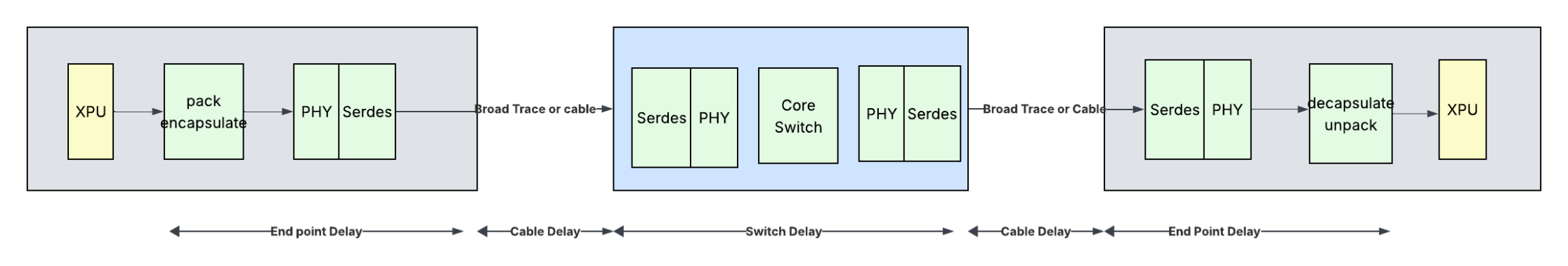
The end-to-end delay consists of several components that are constant, regardless of the fabric chosen. For example, the Ethernet PHY/SerDes, the cables between the accelerators and switches are such components. With 5m cables, the SUE spec indicates end-to-end latencies of 500ns each way and an RTT of 1 μs for read transactions. The numbers look quite aggressive, as the MAC, PHY, and link layers themselves could take up 100-150ns of the switch delay, leaving ~100ns for packet processing and switching.
A rough estimation of latencies is shown in Table 1.
| Component | Latencies (ns) in UALink fabric | Latencies (ns) in Ethernet fabric with scale-up optimized switches | Latencies (ns) in Ethernet fabric with hybrid scale-up/scale-out switches | Notes |
| XPU: Protocol layer transactions to packets/flits | 25 | 25 | 25 | Should be similar. Depends heavily on the Micro-architecture and process node |
| XPU->switch: DL(MAC)/Phy/ SerDes (tx-rx pair) | 150 | 150 | 150 | Identical SerDes / PHY for both UALink and Ethernet |
| 5m Twinax copper | 23 | 23 | 23 | |
| Switch | 75 | 100 | 200 | Depends heavily on the switch radix, buffering, micro-architecture, and process node Cut through processing (Ethernet) Challenging to get below 200ns for Ethernet — if the same switch were to be used in scale-up and scale-out and has deeper pipelines for some scale-out features Ethernet switches targeted for scale-up (with support for only 1K end points) could have similar latencies to UALink (~100ns) |
| Switch->XPU: DL/Phy/SerDes (tx-rx pair) | 150 | 150 | 150 | Cut through MAC, identical SerDes/Ethernet PHY for both UALink and Ethernet |
| 5m Twinax copper | 23 | 23 | 23 | |
| XPU: Packets/flits to protocol layer transactions | 25 | 25 | 25 | Should be similar. Depends heavily on the Micro-architecture. |
| End-to-end (each way) | ~471 | ~496 | ~596 | |
| RTT (for reads) | ~942 | ~992 | ~1,192 | Ethernet purpose built scale-up: 5% additional latency than UALink |
Table 1 — Approximate component latencies.
All things being equal, the Ethernet switches purpose-built for scale-up could have 5% additional RTT latencies. As for the jitter, reducing variations in the sender’s packet sizes in Ethernet switches can help minimize the jitter.
Packet ordering
Ethernet switches support per-flow ordering, where the source/destination addresses and the traffic class fields can determine the flow. With this capability, strict order can be preserved on request and response channels (when they map to different traffic classes) between any pair of accelerators.
Link efficiency (or bandwidth efficiency)
Bandwidth efficiency measures the fraction of total bits or bytes transmitted on a communication link that carry useful data (in this case, memory read or write data).
There is a fine balance between efficiency and latency goals. If the goal is to keep absolute minimal latencies and not wait for multiple transactions to pack them together to reduce the protocol overheads, then efficiencies could get lower.
In the SUE framework, using the new AI header, the overhead is as follows:
- 20B (12B inter packet gap, 7B preamble, 1B delimiter).
- 6B AI header.
- 8B reliable header.
- 4B R-CRC and 4B Frame Check Sequence (FCS).
Reduced inter-packet gap (IPG) of 8B is possible on short, high-quality links if both endpoints support it.
Table 2 shows the byte efficiencies for different frame sizes in the SUE Framework.
| Transactions | Frame size (B) | Fixed overhead (B) | Variable overhead of commands (B) | Total bytes | Bandwidth efficiency |
| 1 | 256 | 42 | 18 | 316 | 81.0 |
| 2 | 512 | 42 | 36 | 590 | 86.8 |
| 3 | 768 | 42 | 54 | 864 | 88.9 |
| 4 | 1,024 | 42 | 72 | 1,138 | 90.0 |
| 5 | 1,280 | 42 | 90 | 1,412 | 90.7 |
Table 2 — SUE efficiency when carrying 256B transactions.
If the Ethernet frame carries only a single 256B read/write data, the bandwidth efficiency is ~81%. However, in typical AI training/inference workloads, the data that is exchanged between the GPUs on any fabric plane is around 2KB or more. This is chopped into multiple 256B transactions. And there is usually more than one 256B transaction to a destination accelerator. The accelerators’ fabric interface logic can aggregate multiple of these transactions destined for the same output port in a single Ethernet frame, thus creating larger frames. The packing inside these larger frames can be very efficient (91% for 5x 256B transactions).
The place where SUE has an advantage is when the transactions are less than 256B and not multiples of 64B boundaries. Since SUE does not have the concept of flits, these non-256B transactions can be packed very tightly back to back without flit fragmentation overheads. The packing logic is implementation dependent.
In UALink, there is a 32-byte control half-flit that carries the requests/write acks and flow control information for every transaction. And if there are multiple write requests to a destination, more than one request can be packed in each control half-flit.
UALink transactions are two-sided. Each standard write request (16B) has a response (8B), and that also adds to the efficiency loss. UALink protocol allows the request/responses to be compressed (when the addresses are cached on both sides, the requests do not need to carry all bits of the memory address).
Table 3 shows the efficiencies (assuming no compression on requests or responses).
| Transactions | Payload size (B) | ~ DL efficiency | Control half-flits | Total Bytes | Bandwidth efficiency (%) |
| 1 | 256 | 0.98 | 1 | 288 | 87.1 |
| 2 | 512 | 0.98 | 2 | 576 | 87.1 |
| 3 | 768 | 0.98 | 3 | 864 | 87.1 |
| 4 | 1,024 | 0.98 | 4 | 1,152 | 87.1 |
| 5 | 1,280 | 0.98 | 5 | 1,440 | 87.1 |
Table 3 — UALink Efficiency without compression. A 32-byte control word contains a 16-byte write request and an 8-byte write response. While the responses are in the opposite direction, their overhead needs to be accounted for. I’ve included it here for simplicity.
The efficiencies improve with compressed headers as shown in Table 4.
| Transactions | Payload size (B) | ~ DL efficiency | Control half-flits | Total bytes | Bandwidth efficiency (%) |
| 1 | 256 | 0.98 | 1 | 288 | 87.1 |
| 2 | 512 | 0.98 | 1 | 544 | 92.2 |
| 3 | 768 | 0.98 | 2 | 832 | 90.5 |
| 4 | 1,024 | 0.98 | 2 | 1,088 | 92.2 |
| 5 | 1,280 | 0.98 | 2 | 1,344 | 93.3 |
Table 4 — UALink with compressed write requests (8B) and write response (4B). More requests can be packed inside a single control flit.
This packing logic can be complex, and the efficiency depends heavily on traffic patterns and implementation. The address compression by caching can be used in any protocol, and the SUE can also benefit from this if the endpoint protocol supports compression.
When the transactions are less than 256B, UALink may have more overhead due to byte-enables and the 64B fragmentation overhead. Table 5 shows the efficiencies for 128B transactions. Transactions that are not multiples of 64B (like 129B, and so on) will have even more inefficiencies, but those are not common in these workloads.
| Transactions | Payload size (B) | Control half-flits | Data half- flits | Total bytes in UALink | Efficiency UALink (%) | Total bytes in Ethernet | Efficiency Ethernet (%) |
| 1 | 128 | 1 | 5 | 192 | 65.3 | 188 | 68.1 |
| 2 | 256 | 2 | 9 | 352 | 71.3 | 334 | 76.6 |
| 3 | 384 | 3 | 13 | 512 | 73.5 | 480 | 80.0 |
| 4 | 512 | 4 | 17 | 672 | 74.7 | 626 | 81.8 |
| 5 | 640 | 5 | 21 | 832 | 75.4 | 772 | 82.9 |
Table 5 — 128B transactions in UALink and SUE.
The UALink protocol allows the DL flit (the 640B tightly packed flit) transmitted between the accelerator and the switch to have transactions destined for different accelerator endpoints. This flexibility allows full packing of the DL flits and increases the link use between the accelerator and the switch ports. With Ethernet, multiple transactions can be packed together inside a single Ethernet frame only if they are all headed to the same destination accelerator.
Thus, the bandwidth efficiency in each interconnect depends heavily on:
- Addressing caching. UALink assumes this is the default mode and that compressed headers can be used most of the time. While it is not explicitly called out in the SUE spec, caching can be implemented in end-points to reduce the command overhead in SUE as well.
- Transaction size.
- Traffic pattern — Are there enough transactions in the queues to pack efficiently (in case of UAlink, this involves packing inside the 32B control half-flit, and in case of Ethernet, packing multiple transactions inside a frame).
Power/area
The IO logic, with 200G PAM4 SerDes, could potentially consume a third to half the power of the switch in both Ethernet-based and UALink-based switches. The power comparison for the switching logic die depends entirely on the implementation and the process node.
Unified scale-up/scale-out?
Although it is explicitly absent from the SUE framework specification, Ethernet switches enable building unified networks for scale-out/scale-up. For example, Microsoft uses this strategy when building the network using its MAIA 100 accelerator. They mention a custom ‘RoCE’-like protocol for memory reads/writes between the accelerators. A low-latency Ethernet switch allows this flexibility if the accelerators choose to build unified networks. However, there is a broad consensus that optimizing the fabrics separately for the unique demands of scale-up and scale-out communication currently offers the best path to maximizing performance for diverse AI workloads, even if it means managing heterogeneous fabrics in the data centres.
Readiness
How about timelines?
The link-level retry and credit flow control features are already well-defined in UEC, and several IP vendors have begun supporting them. According to the Broadcom Senior Vice President’s LinkedIn post, Broadcom may have already implemented switches using the SUE framework, with silicon availability later this year. If it is on track, it gives Broadcom’s Ethernet solutions a one-year lead over UAL switches.
Would the accelerator vendors/hyperscalers continue with their current mechanisms and adopt UALink in their next-generation accelerators or bet on low-latency Ethernet switches using SUE? We will have to see…
An ultra-low-latency Ethernet switch that supports a lossless fabric with reliable links, credit-based flow control at the link layer, and a custom header is a compelling alternative to NVLink or UALink for scale-up. Ethernet can also enable hyperscalers and data centres to use the same switch silicon for both scale-up and scale-out networks if the switch supports the typical scales/features needed for scale-out without compromising on the latencies.
| Criteria | UALink fabric | Ethernet fabric |
| Scale | 1,024 accelerators | 1,024 accelerators |
| PHY | Ethernet PHY (with slight modifications to reduce the latency) | Ethernet PHY (can have similar enhancements to reduce the latency) |
| Data link frame size | Fixed 640B | Variable — up to 4,096B |
| One-sided? | Yes | Yes |
| Credit flow control per class/channel | Yes | Yes |
| Transaction size | 256B | 256B |
| One-sided? | No. Writes have responses too | Yes |
| Transport level retry | No | Variable-sized packets |
| Requests/responses isolation | Virtual channels | Virtual channels (that map to different traffic classes inside the switch) |
| Per accelerator pair/per port and per channel. The protocol also allows ordering only within the 256-byte address boundaries, which the switches can implement | 64B TL Flits | Variable-sized packets |
| Ordering | Depends heavily on traffic patterns. Up to 95% for 5 X 256B writes. Could have inefficiencies if the transaction sizes are smaller than 256B or non-multiples of 64B | Difficult to implement relaxed ordering based on address boundaries. The Ethernet switches can support per accelerator pair/per port and per channel ordering using flow-based ordering |
| End-to-end Latencies | Depends heavily on traffic patterns. Up to 95% for 5 X 256B writes. Could have inefficiencies if the transaction sizes are smaller than 256B or not multiples of 64B | Depends heavily on traffic patterns. Up to 91% for 5 X 256B writes. Depending on implementations, less fragmentation overhead for variable-length transactions. |
| ~1us for switches optimized for scale-up ~1.2us for switches targeted for hybrid scale-up/scale-out | Slightly less than 1us | It could be more, especially if the packet sizes vary. It can be controlled by keeping the packet size ranges tight. |
| Jitter | Less | While the SUE framework specifies one method of sending transactions using Ethernet, the endpoints can define how the payload looks inside the Ethernet header. More flexibility allows the re-use of existing protocols. |
| Allow proprietary protocols | No | While the SUE framework specifies one method of sending transactions using Ethernet, the endpoints can define how the payload looks inside the Ethernet header. More flexibility allows the re-use of existing protocols. |
Table 6 — Comparison summary.
Summary
The industry is at a crossroads.
The future UALink switches can offer efficient, deterministic performance and minimal overhead for memory-centric operations. Ethernet is not far behind with its low latency and link reliability enhancements. UALink silicon is expected to be available in the second half of 2026. Ethernet seems to have a slight time-to-market advantage with low-latency SUE switches expected in ~2H 2025.
Ultimately, industry adoption hinges on workload requirements, balancing specialization (UALink) against ecosystem flexibility and compatibility (Ethernet), the availability of controller IPs for integration in accelerators, and the general availability, cost, and power of the Ethernet and UAL switches.
Both UAL and Ultra Ethernet have merits and tradeoffs, and in the long run, both solutions may continue to coexist.
Any thoughts?
Sharada Yeluri is a Senior Director of Engineering at Juniper Networks, where she is responsible for delivering the Express family of Silicon used in Juniper Networks‘ PTX series routers. She holds 12+ patents in the CPU and networking fields.
Adapted from the original post at LinkedIn.
The views expressed by the authors of this blog are their own and do not necessarily reflect the views of APNIC. Please note a Code of Conduct applies to this blog.