You may have had an opportunity to read my post ‘GPON power budget calculations‘ published on the APNIC Blog last month. This time, I have something similar to share but for Dense Wavelength Division Multiplexing (DWDM). This topic primarily targets DWDM network designers and planners who must estimate optical power levels at various input and output points across the entire link, segment, or network. These estimates are crucial before authorizing deployment, installation, or commissioning teams to validate them in the field.
Ideally, theoretical and practical values should match with only minor deviations and the system should be balanced in terms of power values. Otherwise, debugging a live network and identifying the causes of imbalance becomes challenging. That’s why we have the practice/phase of ‘Acceptance Testing’ before handing everything to the operations team.
DWDM brief introduction
Let me first describe very briefly what is DWDM for those who are not familiar with it before starting my actual topic.

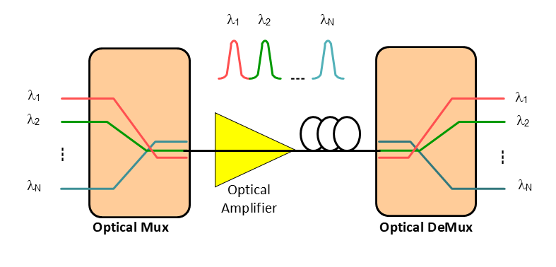
DWDM is a fibre medium-based technology in which multiple wavelengths are multiplexed inside the fibre to carry various communication channels (each wavelength is a channel). Using multiple virtual fibre channels over a single physical fibre provides a cost-effective solution, conserving resources compared to SDH by reducing the need for fibre cables and expensive equipments.
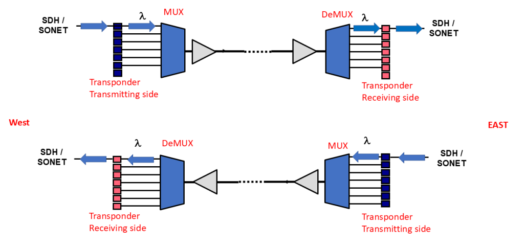
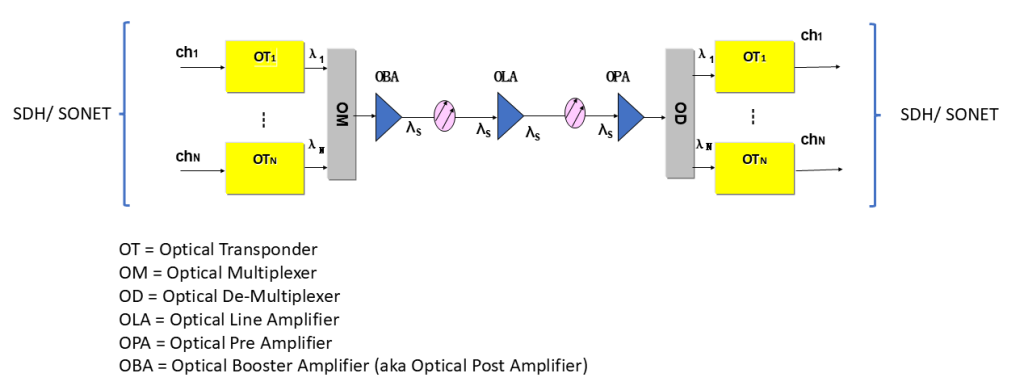
DWDM uses a Multiplexer (Mux) at the transmitting end and a De-Multiplexer (DeMux) at the receiving end, along with optical amplifiers in between, which come in various types and ratings. Optical transponders are typically needed at the input and output of DWDM systems because ingress signals often originate from SDH, requiring the channel wavelength to be converted from standard SDH wavelengths (1,310 nm or 1,550 nm) to the operational band used by the DWDM system. The reversal process is performed at the end of the link to restore the original SDH wavelengths, which then exit toward the SDH equipment. Most components of a DWDM system are passive (without need of external power and electronic circuitry), making DWDM systems more cost-effective compared to SDH.

What is optical power balancing?
As mentioned above, one of the important expectations from DWDM network designers/planners is to estimate the optical power values at various ingress/egress points of the system and come up with a power-balanced end-to-end system (theoretically) before rolling it out, with only minor adjustments needed during field deployment. The more realistic the calculations, the easier it is to debug the system during the Acceptance Testing stage, as the actual values will closely match the estimates — assuming site surveys were conducted accurately.
I had the privilege of working with experienced designers and planners who were remarkably accurate in their estimates for a system spanning approximately two thousand kilometres (from south to north Pakistan). Before diving into a simple calculation example, it is essential to understand concepts such as channel power difference, power units, optical amplifier ratings, and the insertion loss of Mux and DeMux.

Channel power difference
A DWDM system is a multi-wave system, meaning multiple waves are transmitted through the fibre. Therefore, it is important that each wave has matched optical power. It is advisable to keep the optical power difference between any two wavelengths below 4dB. The smaller the difference, the better the outcome, as this helps avoid the need for workarounds.
Power units
A Decibel (dB) is the logarithmic ratio between the output power to the input power.
Power in dB = 10log10 (POUTPUT / PINPUT)dBm is the physical unit, also known as Absolute Power. It is the measurement of power in decibels using 1 mW as the reference point.
Power in dBm = 10log10 (P / 1 mW)Optical amplifiers and their ratings
Three types of amplifiers commonly found in a DWDM system design are Optical Booster Amplifier (OBA), Optical Pre-Amplifier (OPA), and Optical Line Amplifier (OLA). OLA is primarily used in long-haul deployments and may be used in multiple units, depending on the fibre length. It helps reduce span loss and improves the noise performance of the transmission line by boosting the optical signal in transit.
As an example, if you see OBA2420, the first two digits (24 in this case) represent the booster amplifier gain in dB, while the last two digits (20 in this case) indicate the maximum output power of the booster amplifier in dBm.
Similarly, for OPA1512, the first two digits (15 in this case) represent the pre-amplifier’s gain in dB, and the last two digits (12 in this case) represent the pre-amplifier’s maximum output power in dBm.
Insertion loss of Mux and DeMux
The insertion loss of Mux can be calculated by this formula while doing system debugging:
Moutput = 10logPm – Insertion Loss
& 10logPm = 10logPi + 10logN …………. {Pm = Pi x N}
Where:
- Moutput = Mux Output
- Pm = Total multiplexed input power of Mux before insertion loss
- Pi = Optical power of each wavelength (coming from optical transponders)
- N = Number of input wavelengths
Similarly, the insertion loss of DeMux can be calculated as follows:
Doutput = 10logPm – Insertion LossWhere:
- Doutput = DeMux Output
- Pm = Total multiplexed input power of DeMux before insertion loss
A simple example of optical power balancing
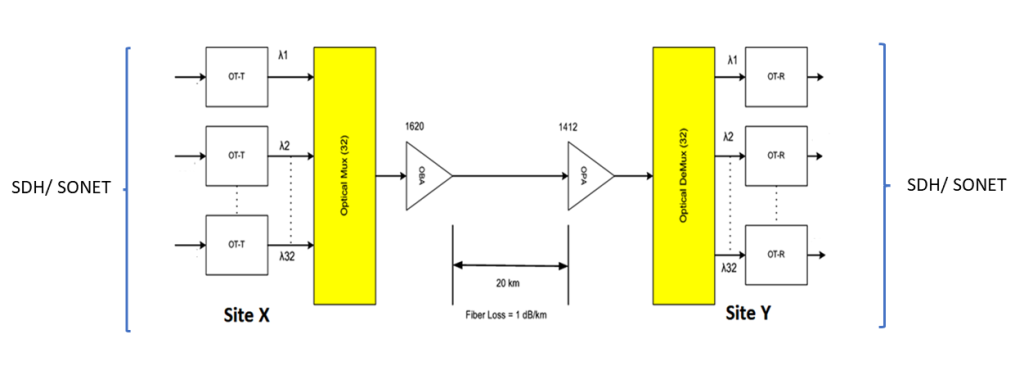
For learning purposes, let’s calculate the attenuator values and their locations to balance the power in a 32-wavelength system. Currently, the system is using five wavelengths (out of 32). APD-type sensitivity devices are used, which operate best at -14 dBm. The transponder output power is -3 dBm.

In a system with 32 channels, 5 channels are currently used. The goal is to determine the value and location of the attenuators.
System parameters
- Transponder output power: -3 dBm
- Mux insertion loss: 7 dB
- DeMux insertion loss: 7 dBm
- Required Transponder receiving sensitivity: -14 dBm
- OBA1620: Gain = 16 dB, Maximum output power = 20 dBm
- OPA1412: Gain = 14 dB, Maximum output power = 12 dBm
- Distance between sites X and Y: 20km
- Fibre loss rate: 1 dB per km
Logarithmic calculations
- 10log32=15
- 10log5=7
Mux calculations
Input power of mux:
- Pm = Pi x N or 10logPm = 10logPi + 10logN
- 10logPi = -3 dBm & 10log5 = 7dBm (N=5)
- therefore; 10logPm = -3+7 = 4 dBm
Mux output:
Moutput = 10logPm – insertion loss, therefore; Moutput = 4-7 = -3 dBm
OBA calculations
Input power of OBA:
- Input power of OBA = maximum output power – gain
- Input power of OBA = 20 – 16 = 4 dBm
Power of channels:
- Power of 32 channel OBA = power of 1 channel OBA + 10log32
- Power of 1 channel OBA = power of 32 channels OBA – 10log32
- Power of 1 channel OBA = 4 – 15 = -11 dBm
- Power of 5 channel OBA = power of 1 channel OBA + 10log5 = -11+7 = -4 dBm
OBA input demands -4 dBm whereas Mux output provides -3 dBm, so we need an attenuator at input of OBA of value 1 dB.
OPA calculations
- OPA input power = OBA output power – line loss
- OPA input power = 20 -20 = 0 dBm
- OPA input power = OPA output power – OPA gain = 12 – 14 = -2 dBm
So, the required OPA input power is -2 dBm but we have 0 dBm so we need an attenuator at input of OPA of value 2 dB.
OPA output:
This 12 dBm OPA output power is for 32 channels so for one channel:
- Power of 32 channel OPA = power of 1 channel OPA + 10log32
- Power of 1 channel OPA = 12-15 = -3 dBm
- Power of 5 channel OPA = power of 1 channel OPA + 10log5 = -3+7 = 4 dBm
DeMux calculations
- Output power of DeMux = power of 5 channel OPA – insertion loss
- Output power of DeMux = 4-7 = -3 dBm (for 5 channels)
- Output power of DeMux (5 channels) = Output power of DeMux (1 channel) + 10log5
- Output power of DeMux (1 channel) = -3-7 = -10 dBm
But APD requires -14 dBm, therefore,
Solution:
Option 1: Insert a 4 dB attenuator at the input of every transponder receive card.
Option 2: Insert a 4 dB attenuator at the input of the DeMux.
Recommendation: The second option is better as it saves the need for multiple attenuators.
In my next post, I will get into bandwidth calculations of GPON. I hope you enjoyed reading this blog. Please keep learning and broadening your knowledge using the resources and training offered by APNIC.
Azhar Khuwaja is a Telecom/IT Trainer with over 20 years of industry and training experience.
The views expressed by the authors of this blog are their own and do not necessarily reflect the views of APNIC. Please note a Code of Conduct applies to this blog.

Excellent, excellent post. Thank you for taking the time to graciously and generously sharing this. Immensely appreciated. Cheers and Best Wishes.
Appreciate your interest. Thank You