Gigabit Passive Optical Network (GPON) is not a new topic. However, its challenges, along with its benefits, remain relevant. I recently visited an Access Network operator in Islamabad, with whom I had previously worked as a vendor trainer. During the meeting, I was asked to simplify the concept of power budget calculations for new hires, and I was happy to oblige. I decided to share my brief discussion on power budget calculations and related parameters with APNIC blog readers as well.
GPON/Access Network brief introduction
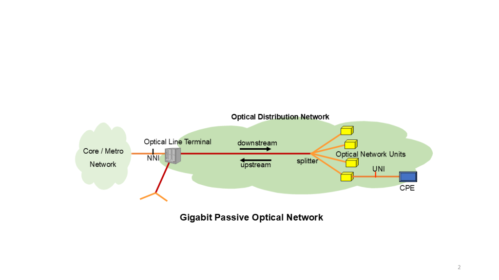
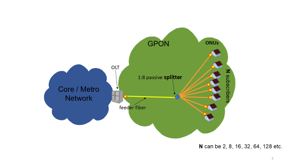
Let me first describe very briefly what GPON is for those who are not familiar with it. GPON is a type of Access Network, similar to Gigabit Ethernet Passive Optical Network (GEPON), which provides various services to end users through a local network. It covers a relatively small geographical area and is designed to deliver services to home and office users, corporate customers, and enterprises, primarily using fibre as the medium. GPON has a mostly distributed architecture and can typically support 32, 64, 128, or more end-users.
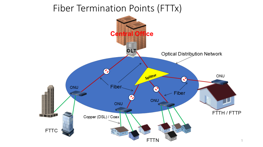
The Optical Distribution Network (ODN) defines the structure of the Access Network and supports various termination points (Fibre to the X, or FTTx), depending on the implementation, including Fibre to the Home (FTTH), Fibre to the Curb (FTTC), and Fibre to the Node (FTTN). International Telecommunication Union Telecommunication Standardisation Sector G.902 (ITU-T G.902) is a framework recommendation outlining the architecture and functions of the Access Network.

Gigabit Passive Optical Network (GPON) is based on the ITU-T G.984.x standards and typically allows 64 to 128 splits with an approximate reach of 20 km. It supports triple-play services, offering high bandwidth and long reach at low cost. GPON is also easy to troubleshoot and maintain due to its passive nature, with no active appliances in its structure.

Relationship between transmission distance and number of splits
One of the key considerations for every GPON designer is the achievable span between the Optical Line Terminal (OLT) and the subscribers — that is, the maximum optical budget allowed in the system. The optical budget consists of losses due to splices, connectors, fibre, and optical splitters. The optical splitter is by far the most significant contributor to loss. For example, a typical 1 x 32 optical splitter may have an insertion loss ranging from 17 dB to 18 dB. This is notably high compared to losses caused by other components in GPON, yet it must be accepted as there is no substitute for the optical splitter. In fact, it is the splitter that makes GPON a cost-effective solution and simplifies its architecture.
Loss values vary depending on the type of splitter, such as Planar Lightwave Circuit (PLC) or Fused Biconic Taper (FBT) types. The optical splitter is a passive device and is straightforward to work with (Figure 3). However, the higher the number of splits offered by the splitter, the greater the optical power loss. In other words, GPON designers must carefully justify their choice of splitter with a specific number of outputs in their design. The greater the number of splits, the higher the loss from the optical splitter, which in turn reduces the maximum distance achievable between the OLT and the Optical Network Units (ONUs).

Power budget
Optical power budget refers to optical technologies that use fibre as the transmission medium, carrying light instead of voltages and currents, as seen in electrical communication. It accounts for all the gains and losses within an optical communication system, making it a challenging task for network designers and planners. A properly power-budgeted network results in fewer complications and maintenance issues. Without accurate power budget calculations, the receiving device in the network may experience issues: too much power can damage its detector, while too little power may prevent detectors from sensing optical signals properly or lead to high error rates in data detection.
A GPON system consists of an OLT, ONUs, and an ODN that connects the OLT to the ONUs. The ODN’s characteristics, such as losses, are critical and consist of passive optical elements like single-mode fibres, connectors, passive branching components, passive optical attenuators, and splices. The power budget takes into account all optical components between the OLT and ONU. The transmitter’s power and the receiver’s sensitivity are two parameters that define the potential reach of the network. To calculate the worst-case power budget scenario, the minimum receiver sensitivity is subtracted from the minimum transmitter power. Using these values, the total network loss is determined, allowing for the calculation of the network’s maximum reach.
Another important term is ‘insertion loss’, which refers to the difference in power between the input and output of a device, such as a splitter. For example, if a splitter receives an input power of 20 dBm and the output is measured at 3 dBm, the insertion loss is 17 dB.
So how exactly this budget estimation is made? The formula for power balance is very simple:
Transmitter power = receiver sensitivity + total lossIn this equation, the total loss is expressed in dB. Fibre attenuation is measured in dB/km, while both splitter loss and penalties (which include splice and connector losses) are measured in dB as well.
There are two common types of receivers: Avalanche Photodiode (APD) and Positive-Intrinsic-Negative (PIN) photodiodes. Typical sensitivity ranges for each type are as follows:
- PIN: Sensitivity ranges from -18 dBm to 0 dBm, with an optimal value of -7 dBm.
- APD: Sensitivity ranges from -28 dBm to -8 dBm, with an optimal value of -14 dBm.
Typical values for laser-based transmitter output power are:
- Short Reach: -3 dBm
- Medium Reach: 0 dBm
- Long Reach: +3 dBm
These are just typical values. For exact transmitter output power and receiver sensitivity, please consult your vendor’s datasheets.
A simple example of power budget calculation
For learning purposes, let’s calculate the fibre length (reach) of a simple network with the following parameters:
- A single-mode fibre with 0.35 dB/km attenuation is used.
- Splitter loss, as per the datasheet, is 14 dB.
- There are two mechanical splices and two connectors in the fibre.
Other parameters:
- Transmitter power = 5 dBm
- Receiver sensitivity = -14 dBm
- Fibre loss = 0.35 dB/km
- Fibre length (Reach) = ?
- Splitter loss = 14 dB
- Splice loss for 2 splices = 2 × 0.1 dB = 0.2 dB
- Connector Loss for 2 connectors = 2 × 0.75 dB = 1.5 dB
Using the formula transmitter power = receiver sensitivity + total loss we resolve:
- 5 = -14 + {Fiber Attenuation per km x distance in km + Splitter Loss + Penalties}
- 19 = 0.35 x D + Splitter Loss + Penalties {where D is distance in kilometers}
- Penalties = Splice Loss + Connector Loss
- Penalties = 0.2 + 1.5 = 1.7dB
- 19 = 0.35 x D + 14 + 1.7
- 0.35 x D = 19 – 15.7
- D = 10 km
So in this example, the reach (distance between OLT and ONU) comes out at approximately ≈ 10km.
In my next blog, I will get into bandwidth calculations of GPON. I hope you benefitted from reading this blog post. Please keep learning and broadening your knowledge using the resources and training offered by APNIC.
Azhar Khuwaja is a Telecom/IT Trainer with over 20 years of industry and training experience.
The views expressed by the authors of this blog are their own and do not necessarily reflect the views of APNIC. Please note a Code of Conduct applies to this blog.

I wonder about latency and jitter as a function of splits?
Yes, splitter offers negative impact on QoS but it is usually 5% or less of total distance between OLT and ONU so the impact is not significant. Feeder fiber covers the majority length between OLT and ONU as it connects OLT with Splitter.
Gigabit Passive Optical Network (GPON) technology is a fiber optic communication system that uses a single optical fiber to serve multiple end-users. It is a cost-effective solution that provides high-speed internet access, IPTV, VoIP, and other services over a single fiber connection.
The benefits of Fiber GPON technology include higher bandwidth capacity, faster speeds, reliability, and scalability. It has become increasingly popular in recent years due to its ability to meet the growing demands for high-speed internet and data services.
Vey much informative.