Ethernet has been the mainstay of much of the networking environment for almost 50 years now, but that doesn’t mean that it’s remained unchanged over that period. The evolution of this technology has featured continual increases in the scale of Ethernet networks, increasing capacity, reach, and connections. I’d like to report on a couple of Ethernet-related presentations that took place at the recent NANOG 92 meeting, held in Toronto in October 2024 that described some recent developments in Ethernet.
Towards 800Ge
The original 1982 10Mbps Ethernet is a distant memory these days. A little over a decade later we saw a 100Mb standard, and five years after that, in 1999, there was Gigabit Ethernet (1GbE). 10GbE followed a further five years later, and 100GbE in 2010. 400GbE was defined in 2017.
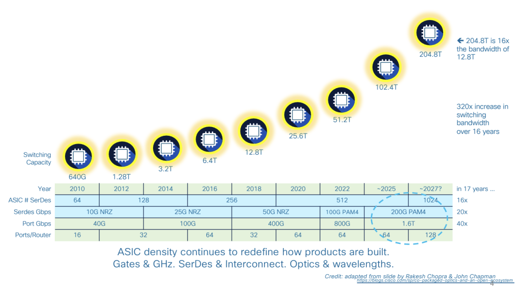
Much of this has occurred by realizing the potential of increasing gate density on silicon chips. Aggregate switching capacity has increased by a factor of 16 in the past decade, from 3.2Tbps to 51.2Tbps. This has been accompanied by an increase in the number of ports per device and the individual port capacity (Figure 1)
Today’s Ethernet systems achieve high capacity by using a parallel approach. The initial 100Gb Ethernet systems used 10 lanes each running at 10Gbps. When the standard for 25Gbps Ethernet was completed, the same 100Gbps system could be constructed using 4 x 25Gbps lanes. This generic approach of using parallel lanes to achieve higher aggregate network capacity is shown in Figure 2.
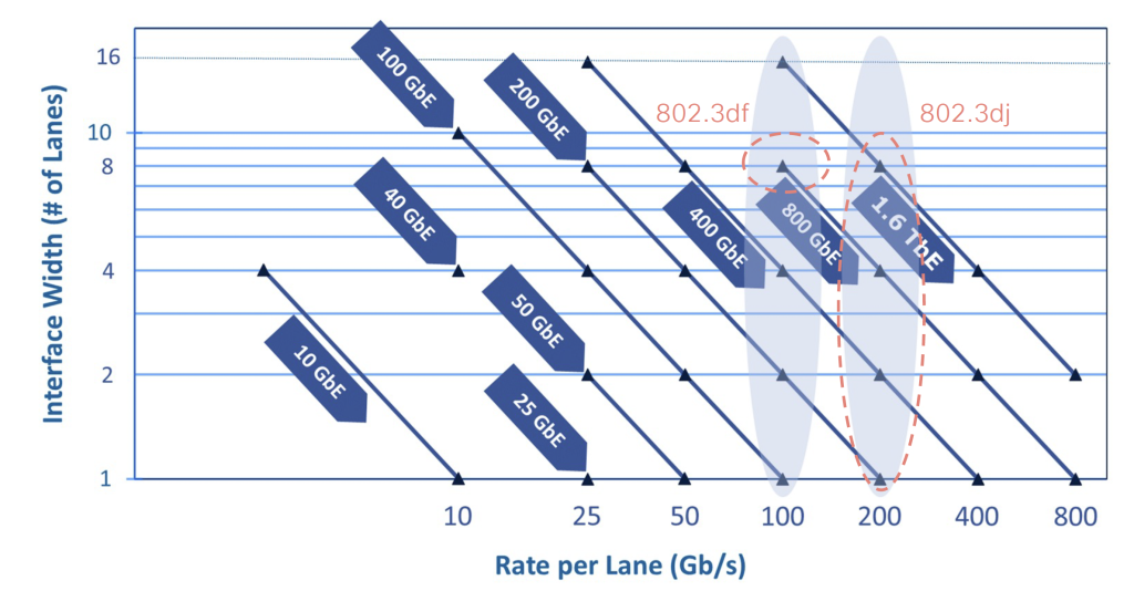
The foundation of today’s production Ethernet networks lies in 100Gbps lanes. When paired up they provide a 200Gbps service, and in groups of four, they provide today’s 400Gb Ethernet service.
The IEEE’s P802.3dj project aims to establish a standard for a 200Gbps Ethernet lane and to define how 2, 4, or 8 lanes can be combined to provide 400GbE, 800GbE, and 1.6TbE Ethernet interfaces. For electrical interfaces, the standard includes specifications for a 200Gbps serial interface, intended for use with copper cables, backplanes, and chip-to-module (AUI) connections. In the case of optical cables, a 200Gbps interface is only specified for single-mode fibre. For short distances between 500 metres and 10 kilometres, a 200Gbps signal is transmitted using Intensity Modulation/Direct Detection (IMDD) with On-Off Keying (OOK) modulation. For longer distances (10 to 40 kilometres), the standard specifies the use of 800Gbps per lane with coherent signalling and 16QAM (quadrature amplitude modulation).
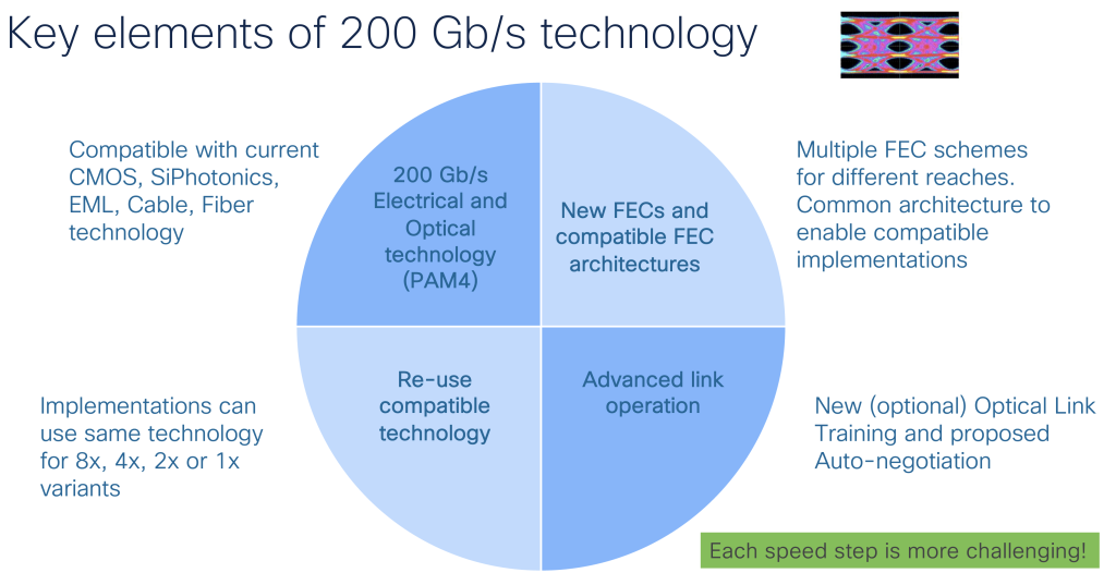
This P802.3dj specification covers most of the current specifications for 100Gbps per lane Ethernet with provision for up to four concurrent lanes, operating over copper cables and fibre cable plant, and is intended to be compatible with current systems.
One of the major changes in the 200Gbps per lane specification is the addition of new (larger) Forward Error Correction (FEC) schemes. FEC schemes used for 100Gbps and slower are retained, and a new FEC scheme is defined for 200Gbps per lane. Much effort has been spent on maintaining backward compatibility with the existing Ethernet plane, as shown in Figure 3.
Where does it go from here?
Increasing the number of lanes provides a performance gain, but it comes at a linear cost multiplier. While multiple lanes increase the aggregate capacity of the network, individual streams still operate within the capacity constraints of an individual lane.
Increasing the per lane capacity of a system offers the potential for greater cost performance of the system. These days the increasing per-lane speeds require faster signal modulation drivers and more capable signal detector systems that operate reliably at lower signal-to-noise levels. This is achieved by using more complex digital signal processors, which require increased gate counts on the ASIC chips and also generally need more power to operate, which in turn, imposes some constraints on the physical packaging of the network interface devices. It appears to come down to silicon capabilities (Figure 4).
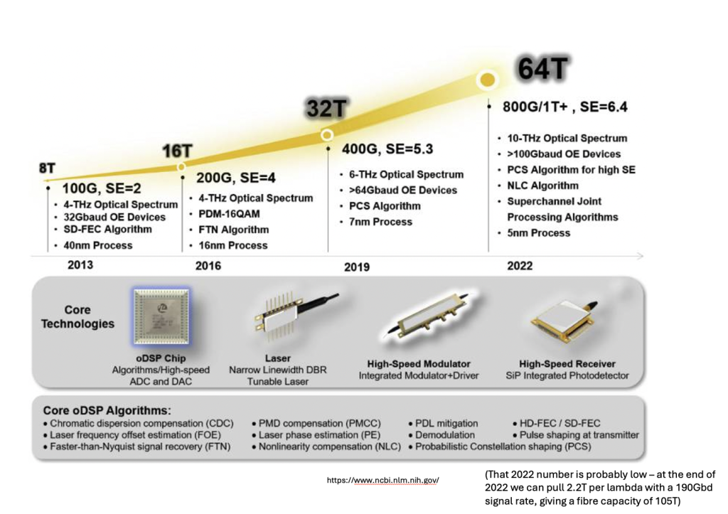
There is still some potential to increase the base speed by extending the signal encoding to use more discrete points in the phase / amplitude space, but it appears that to do so we need to use digital signal processors in chips built using a 3nm process, and this level of size reduction also implies the use of more than simple planar gate design on the chip, such as Gate-All-Arounds (GAAs) and other related approaches that increase the junction areas within each gate within the constraints of narrow track width.
At this stage it not does appear to be outlandish to expect per-lane capacities to increase from 200G to 400G in the coming years. Even higher speeds appear to rely on the use of as-yet-undefined silicon chip technologies that can offer the combination of high yield, reliable operation, increased gate density and more efficient power management.
Ultra Ethernet for AI
There is more to designing performance for very high-capacity local network environments than just the headline number of per-lane speeds. Understanding the nature of the workload that the network must support, and tailoring the network to match that workload is also important. Much of the scaling effort in today’s network infrastructure is focused on the demands being made by large-scale AI platforms.
In very general terms, a local AI network is a large set of GPUs and a set of memory banks, and the network is cast into the role of a distributed common bus to interconnect GPUs to memory in a similar vein that the backplane of the old mainframe computer design was used to connect several processing engines to a set of storage banks (Figure 5). Here Remote Memory Access performance is critical, and the approach, in very general terms, is to enable the network to pass packet payloads directly to the hardware modules that write to memory, and similarly assemble packets to send by reading directly from memory. The current way to achieve this is by Remote Direct Memory Access (RDMA) over Converged Ethernet (RoCE).
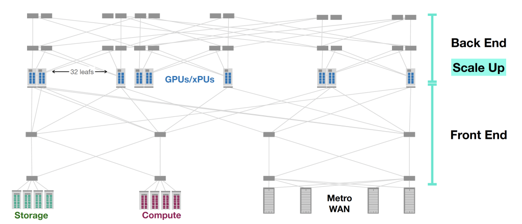
Network-intensive applications like AI, networked storage, or cluster computing need a network infrastructure with a high bandwidth and low latency. The advantages of RoCE over other network application programming interfaces such as the socket abstraction are lower latency, lower processing overheads and higher bandwidth.
However, the concept of using the network for remote memory (Remote Memory Access (RMA)) where it is possible to transfer from one device’s memory to another without involving the operating systems of the two devices is not a new one, and RMA has been around for some 25 years, often seen in parallel computing clusters. However, these approaches had their shortcomings, including the lack of explicit support for multi-pathing within the network (which constrained the network service to strict in-order delivery), poor recovery from single packet failure and unwieldy congestion control mechanisms.
Ultra Ethernet (UE) is not a new media layer for Ethernet but is intended to be an evolution of the RMA protocol for larger and more demanding network clusters. The key changes are the support for multi-pathing in the network and an associated relaxing of the strict in-order packet delivery requirement. It also uses rapid loss recovery and improved congestion control. In short, it appears to apply the behaviours of today’s high-performance multi-path transport-level protocols to the RMA world. The idea is to use a protocol that can make effective use of the mesh topology used in high-performance data centre networks to allow the scaling of the interconnection of GPUs with storage, computation, and distribution networks.
A critical part of this approach lies in multi-path support which is based on dropping the requirement for strict in-order packet delivery. Each packet is tagged with its ultimate memory address, allowing arriving packets to be placed directly into memory without any order-based blocking. However, this does place a higher burden on loss detection within the overall RMA architecture.
UE replaces silent packet discard with a form of signalled discard, similar to the Explicit Congestion Notification (ECN) signalling mechanisms used in L4S in TCP. If a packet cannot be queued in a switch because the queue is fully occupied, the packet is trimmed to a 64-octet header snippet and this snippet is placed into a high-priority send queue. Reception of such a trimmed packet causes the receiver to explicitly request retransmission from the sender for the missing packet, which is equivalent to Selective Acknowledgment (SACK) signalling used in TCP.
UE also proposes the use of fast startup, including adding data payloads to the initial handshake used to establish a flow. This approach eliminates the delay of a round-trip handshake before transmitting, as the connection is established on-demand by the first data packet.
Many networking protocols face the challenge of being generic enough to work across diverse environments. However, when performance optimization is focused on a specific, more limited scenario, further improvements can be made. This is what UE does. It takes the more generic approach of RMA over IP and makes some specific assumptions about the environment and the payload profile that are specific to high-performance data centres used for data-intensive processing, such as AI processing. It’s an interesting approach to scaling in data centres, as it does not attempt to alter the underlying Ethernet behaviours but pulls in much of the experience gained from high-performance TCP and applies it directly to an Ethernet packet RMA management library.
NANOG 92 meeting materials are available online.
The views expressed by the authors of this blog are their own and do not necessarily reflect the views of APNIC. Please note a Code of Conduct applies to this blog.
